Micro area variable angle spectrum test system

A spectrum test and test system technology, applied in the field of spectrum characteristic test, can solve problems such as low resolution of instrument measurement, inability to adjust the receiving angle of detector samples, failure to meet test requirements, etc.

Active Publication Date: 2015-09-09
TECHNICAL INST OF PHYSICS & CHEMISTRY - CHINESE ACAD OF SCI
View PDF6 Cites 0 Cited by
  • Summary
  • Abstract
  • Description
  • Claims
  • Application Information

AI Technical Summary

Problems solved by technology

[0005] (2) Commercialized microspectrophotometers, such as the MSP500 of J&M in Germany and the QDI2020 of CRAIC in the United States, can measure transmission, reflection, and absorption spectra from visible light to near-infrared bands. The measurement scale can be as small as 1 μm, but the instrument The measurement resolution is relatively low, for example, the visible light band is 1nm, and the near-infrared light band is 3.5nm, which is far from meeting the growing testing requirements of micro-nano photonics devices
[0007] Although the above instruments or systems can measure the spectral characteristics of micro-domain materials and structures with a size smaller than, for example, 100 μm, they generally have a common disadvantage, that is, they can only measure the spectrum of the sample in a certain direction, and the light source is relatively large. The angle of incidence of the sample cannot be adjusted, and the angle of acceptance of the detector relative to the sample cannot be adjusted

Method used


Image

  • Micro area variable angle spectrum test system
  • Micro area variable angle spectrum test system
  • Micro area variable angle spectrum test system

Examples


example 1

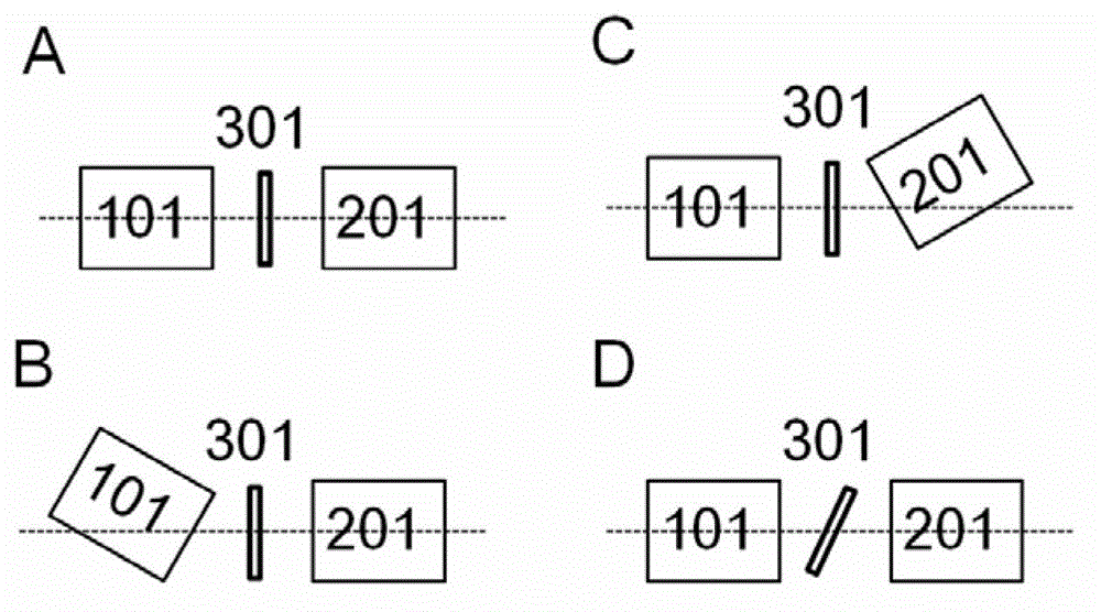
[0052] as figure 2 The transmission spectrum test mode shown in C is an example in which the incident angle is constant and the receiving angle is changed, and the variable-angle micro-area spectrum test system of the present invention will be described in conjunction with the accompanying drawings.

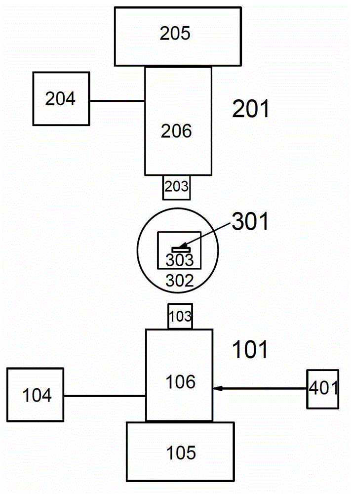
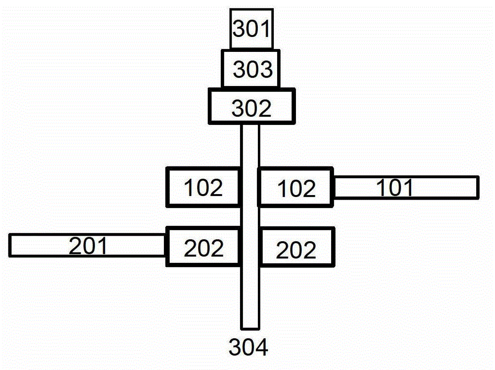
[0053] Select a polymer photonic crystal structure, for example, 40 μm×40 μm in size as a sample, and fix it on the sample stage 301 , which is located on the three-dimensional moving device 303 and can move accordingly. The three-dimensional moving device 303 is located on the sample stage rotating device 302 , and the sample stage and the sample stage three-dimensional moving device can rotate with the sample stage rotating device 302 . In the measurement of the transmission spectrum of the sample, the incident light beam is kept perpendicular to the surface of the sample, the receiving angle is changed by rotating the receiving optical path adjustment device, and the transmis...

example 2

[0058] as image 3 The reflectance spectrum test mode measured when changing the sample stage angle, incident angle and receiving angle shown in C is taken as an example, and the variable-angle micro-area spectrum test system of the present invention will be described in conjunction with the accompanying drawings.

[0059] Select a two-dimensional metal array structure, for example, a size of 30 μm×30 μm as a sample, and fix it on the sample stage 301, which is located on the three-dimensional moving device 303 and can move accordingly. The three-dimensional moving device 303 is placed on the sample stage rotating device 302 , and the sample stage and the sample stage three-dimensional moving device can rotate with the sample stage rotating device 302 . In the reflectance spectrum measurement of the sample, the sample stage rotating device 302 is adjusted to change the incident angle and the receiving angle, and the reflectance spectrum of the sample under different incident a...

example 3

[0064] as image 3 The rotating sample stage shown in B, and the reflectance spectrum test measured when the incident angle is changed are taken as an example, and the variable-angle micro-region spectrum test system of the present invention will be described in conjunction with the accompanying drawings.

[0065] Select a two-dimensional metal array structure with a size such as 30 μm×30 μm as a sample, and fix it on the sample stage 301, which is located on the three-dimensional moving device 303 and can move accordingly. The three-dimensional moving device 303 is located on the sample stage rotating device 302 , and the sample stage and the sample stage three-dimensional moving device can rotate with the sample stage rotating device 302 . In the reflectance spectrum measurement of the sample, the light beam from the light source is incident at a certain angle. By maintaining the incident light path 101 and rotating the sample stage rotation device 303, the incident angle is...


PUM


Abstract

The invention provides a micro-area spectrum test system. The test system comprises an incident light path, a sample bench and a receiving light path. The incident light path comprises an incident microscope objective arranged on the incident light path, a first spectrum test unit and a first real-time observation system. The receiving light path comprises a receiving microscope objective arranged on the receiving light path, a second spectrum test unit and a second real-time observation system. The test system further comprises a sample bench rotating device and a first light path rotating device, wherein the sample bench rotating device is used for adjusting the sample bench to rotate around a rotating shaft perpendicular to the sample bench, and the first light path rotating device is used for adjusting the incident light path or the receiving light path to rotate around the rotating shaft. The micro-area spectrum test system is capable of providing a plurality of spectrum test modes, such as transmission, reflection or fluorescence which are variable in incident angle and receiving angle, to a micro-area sample.

Description

technical field [0001] The invention relates to the field of spectral characteristic testing of micro-nano photonic devices. More specifically, the present invention relates to a micro-zone variable-angle spectroscopic testing system. Background technique [0002] With the rapid development of nanotechnology, the research on various micro-nano materials and structures is becoming more and more diversified, especially the nano-photonic devices represented by photonic crystals, negative refraction materials, plasmonic photonic devices, etc. Functionality and miniaturization. With the reduction of the scale of materials and structures, the development of micro-nano photonics devices is facing testing problems, that is, how to accurately and comprehensively detect the optical properties of various photonic devices at the micro-nano scale, and explore the new phenomena and new phenomena contained in them. mechanism, which has become a bottleneck for the further development of m...

Claims


Application Information

Patent Timeline
Patent Type & Authority Patents(China)
IPC IPC(8): G01J3/28
Inventor 段宣明李敬董贤子
Owner TECHNICAL INST OF PHYSICS & CHEMISTRY - CHINESE ACAD OF SCI
Why Eureka
Try Eureka