A distribution cabinet

A technology for power distribution cabinets and cabinets, which is applied in the field of power distribution cabinets to achieve the effects of tight locking, convenient production and manufacturing, and safe and reliable use

Inactive Publication Date: 2017-05-31
STATE GRID HENAN ELECTRIC POWER COMPANY ZHENGZHOU POWER SUPPLY +11
View PDF7 Cites 0 Cited by
  • Summary
  • Abstract
  • Description
  • Claims
  • Application Information

AI Technical Summary

Problems solved by technology

[0003] However, the power supply bureaus in some areas require the rear sealing plate of the power distribution cabinet to meet the requirements of electrical locking, so as to make the use of the power distribution cabinet safer. However, there is currently no power distribution cabinet on the market that can achieve the electrical locking of the rear sealing plate

Method used


Image

  • A distribution cabinet
  • A distribution cabinet
  • A distribution cabinet

Examples


Embodiment 1

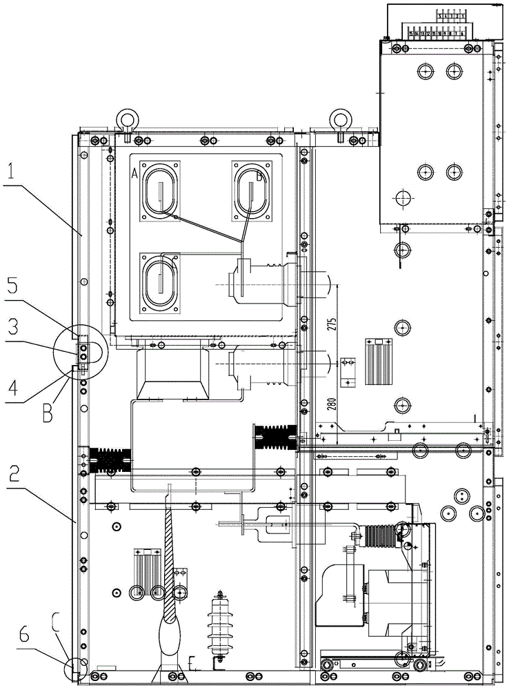
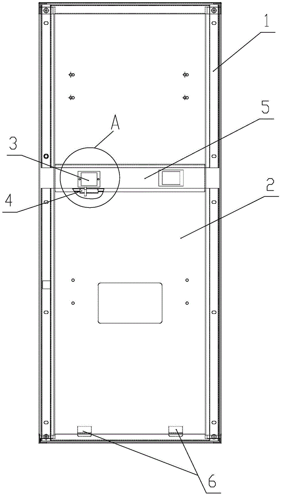
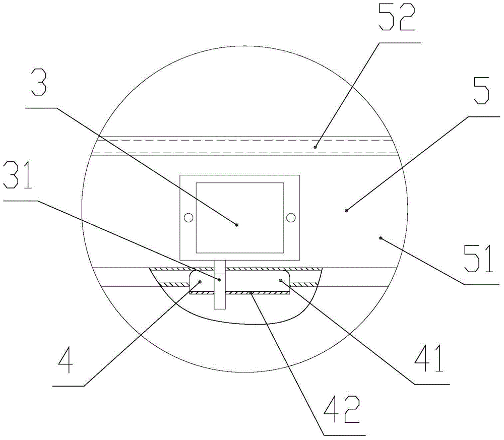
[0038] Figure 1 to Figure 5 It is a schematic structural diagram of the power distribution cabinet provided in this embodiment. As shown in the figure, the power distribution cabinet includes a cabinet body 1 and a rear sealing plate 2 arranged on the cabinet body 1 . An electromagnetic lock 3 is arranged on the inner side of the upper part of the rear sealing plate 2 , and a locking plate 4 is fixedly arranged on the inner side of the rear sealing plate 2 near the position of the electromagnetic lock 3 . The electromagnetic lock 3 is fixed on the cabinet body 1 through the electromagnetic lock bracket 5, and the structure of the electromagnetic lock bracket 5 is as follows: Image 6 with 7 As shown, it includes the base plate 51 and the connecting edge 52 formed by bending the four edges of the base plate 51 respectively. The connecting edge 52 is provided with a number of connecting holes 53, and the electromagnetic lock bracket 5 is connected to the cabinet body 1 through...


PUM


Abstract

The invention discloses a power distribution cabinet and is designed aiming to solve the problems that a rear seal plate of a conventional power distribution cabinet cannot be locked electrically and the like. The power distribution cabinet comprises a cabinet body and a rear seal plate arranged on the cabinet body, wherein an electromagnetic lock is arranged on the inner side of the upper part of the rear seal plate; a lock plate is arranged in a position, close to the electromagnetic lock, in the inner side of the rear seal plate; a lock bolt hole is formed in the lock plate; a lock bolt of the electromagnetic lock can penetrate through the lock bolt hole; at least one insertion plate is fixedly arranged at the lower part of the inner side of the rear seal plate; at least one insertion hole is formed in the position, corresponding to the at least one insertion plate, in the cabinet body; and part of the insertion plates are inserted into the insertion holes. The power distribution cabinet is simple and reliable in structure, the rear seal plate can be electrically locked, and the use is safer.

Description

technical field [0001] The invention relates to a power distribution cabinet. Background technique [0002] The existing rear sealing plate of the power distribution cabinet can meet the mandatory standard of five-proof lockout, that is, to prevent the disconnector from opening and closing with load (the disconnector cannot be operated when the circuit breaker, load switch and contactor are closed); , Mis-closing circuit breakers, load switches, and contactors (only when the operating instructions correspond to the operating equipment can the operated equipment be operated); prevent the circuit breaker and load switch from being closed when the grounding switch is in the closed position (only when the grounding switch is in the open state) , to close the isolating switch or handcart to enter the working position, and operate the circuit breaker and load sharing switch to close); prevent the grounding switch from being mistakenly closed when electrified (only when the circuit...

Claims


Application Information

Patent Timeline
Patent Type & Authority Patents(China)
IPC IPC(8): H02B1/26H01H9/20
Inventor 董锐牛罡朱莉张延辉杨凤民梁青云刘小兵周政张博钊杨岚清
Owner STATE GRID HENAN ELECTRIC POWER COMPANY ZHENGZHOU POWER SUPPLY
Why Eureka
Try Eureka