
Device for attaching chain links

A chain link and chain technology, applied in the direction of drag chain, hanging chain, transmission chain, etc., can solve the problems of high tilting risk and jamming.

Active Publication Date: 2014-01-22
RUD KETTENFABRIK RIEGER & DIETZ GMBH & CO
View PDF15 Cites 4 Cited by
  • Summary
  • Abstract
  • Description
  • Claims
  • Application Information

AI Technical Summary

Problems solved by technology

[0005] The disadvantage of recent prior art is the high risk of tipping
Especially at high loads there is a risk of the end link rotating to the edge of the retaining segment and then jamming

Method used


Image

  • Device for attaching chain links
  • Device for attaching chain links
  • Device for attaching chain links

Examples


Embodiment Construction

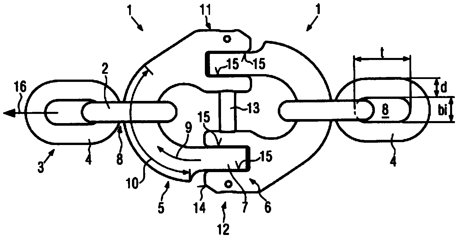
[0044] First, the design of the device 1 connecting the end links 2 of the chain 3 is described. The chain 3 consists of substantially annular closed chain links 4 and can be short or long. The chain 3 can in particular be a round steel chain or a profiled chain. The geometry of the chain link 4 is preferably derived from relevant standards, such as DIN EN 818-4.

[0045] The geometry of the device 1 is respectively defined or predetermined by the geometry of the chain links 4 . The device 1 is preferably for a very specific type and a very specific size of the chain 3 respectively.

[0046] Just to give an example, figure 1 Two identical devices 1 are shown mirrored pivotally connected to each other and form a connecting coupling of two chains 3 .

[0047] The device will be described below according to figure 1 Device 1 on the left explained. for figure 1 For the device on the right, the following description also applies respectively.

[0048] The device 1 comprises...


PUM


Abstract

The invention relates to a device (1) for attaching an end link (2) of a chain strand (3) made of chain links (4) of a predetermined geometry. The device comprises a retaining device (5) comprising an insertion segment (7) at one end (6) that can be inserted in an opening (8) of the end link, and a retaining segment (5). The retaining segment comprises a cross section (28) on which the end link can be placed in a limited number of retaining positions, preferably only one single retaining position, from the insertion segment (7). The device further comprises a closure element (12) by which the end link can be permanently secured to the retaining device. In order to prevent tilting of the end link on the retaining device during operation, according to the invention the closure element forms a stop (14) by which a motion of the end link out of the retaining segment (10) in the direction of the insertion segment (7) is blocked.

Description

technical field [0001] The present invention relates to a device for connecting end links of a chain made of links of a predetermined geometry, having at least one retainer comprising at least one end at least one insert segment in from at least one end of the insertion section insertable into the opening of the end link, and comprising at least one retaining section, wherein the retaining section comprises a cross-section in which the end link can be placed in a limited number of retaining positions from the insertion section, And having at least one closure element by which the end link can be permanently secured to the holder. The device according to the invention is especially designed for circular steel chains or profiled steel chains. Background technique [0002] For connecting the end links of a chain, for example couplings are known. Such connection couplings are shown in DE2805917A1, DE3803250C1, DE82466U1, DE31d970A1, DE3314075A1, DE8136770U1, DE19619831A1 and D...

Claims


Application Information

Patent Timeline
IPC IPC(8): F16G13/12F16G15/04
CPCF16G13/12F16G15/04F16G13/08
Inventor 迈克尔·贝茨勒罗兰·雅库贝茨
Owner RUD KETTENFABRIK RIEGER & DIETZ GMBH & CO
Learn More