
Orthodontic anchoring module and its orthodontic plate and surgical guide device

A technology of surgical guidance and correction plate, applied in the direction of brackets, etc., can solve the problems of loss of anchoring effect of bone nail 9, difficulty in reducing the axial height, and collapse of the jawbone

Inactive Publication Date: 2016-02-24
I-SHOU UNIVERSITY
View PDF7 Cites 0 Cited by
  • Summary
  • Abstract
  • Description
  • Claims
  • Application Information

AI Technical Summary

Problems solved by technology

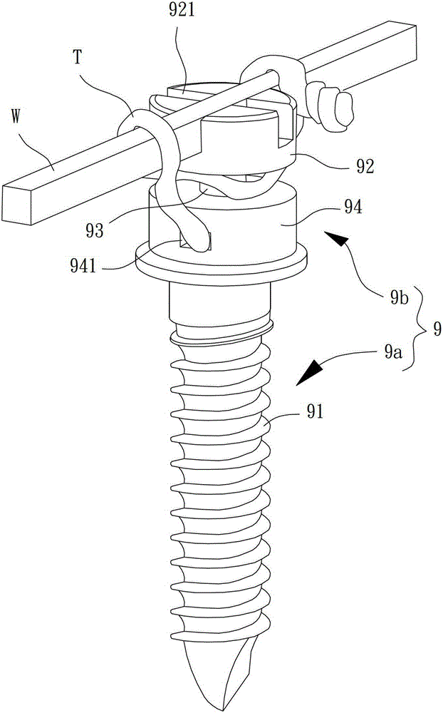
[0004] On the other hand, since the existing bone screw 9 needs to provide the functions of penetrating and correcting the steel wire W, the square twisted wire T and hooking the elastic element at the same time, the head 92 of the bone screw 9, the necking part 93 and the threading Both parts 94 need to maintain a preset height, so that the axial height of the exposed section 9b of the bone nail 9 is difficult to reduce. Not only will it excessively interfere with the patient's lips and gums and increase the discomfort, but the greater the distance between the necked part 93 and the gums , the more the torque generated by the square strand T and the elastic element is increased, the implanted section 9a of the bone nail 9 will produce a contact relationship with a local high stress value on the jawbone, thereby improving the local collapse of the jawbone. chance, causing the existing bone nail 9 to lose its anchoring effect, affecting the effect of corrective treatment

Method used


Image

  • Orthodontic anchoring module and its orthodontic plate and surgical guide device
  • Orthodontic anchoring module and its orthodontic plate and surgical guide device
  • Orthodontic anchoring module and its orthodontic plate and surgical guide device

Examples


Embodiment Construction

[0053] In order to make the above-mentioned and other objects, features and advantages of the present invention more comprehensible, the preferred embodiments of the present invention are specifically cited below, together with the accompanying drawings, as follows:

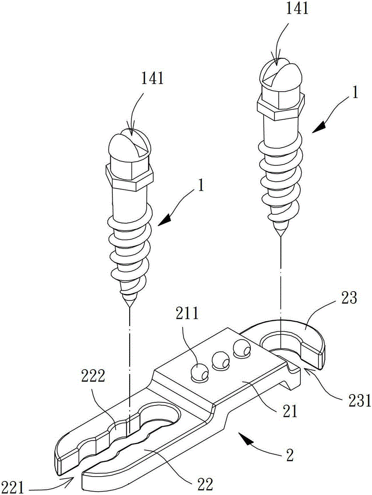
[0054] see figure 2 , which is a preferred embodiment of the present invention, the orthodontic anchoring module includes two bone screws 1 and an orthodontic plate 2, the two bone screws 1 can be respectively locked and implanted in the jawbone, and the orthodontic plate 2 can be placed on the gum The two bone nails 1 are overlapped on the surface.

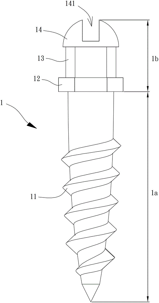
[0055] Please refer to image 3, each of the bone screws 1 has an implanted section 1a and an exposed section 1b connected to each other, and the implanted section 1a can be provided with a threaded portion 11; 11 The drill lock is combined in the jawbone and gums, and the exposed section 1b of the bone nail 1 remains exposed outside the gums.

[0056] The bare ...


PUM


Abstract

This invention discloses an orthodontics correction anchoring module, comprising a bone nails and a correction plate. The bone nail comprises an exposed segment and an implanting segment which are connected. The exposed segment is provided with a first twistlock part, a buckling part and a second twistlock part. The first twistlock part is in proximity of the implanting part of the bone nail. The circumferential surface of the first twistlock part is not circular. The buckling part is positioned between the first twistlock part and the second twistlock part. The correction plate comprises a gapping segment, a positioning segment and a turn-lock part. The gapping segment is positioned between the positioning segment and the turn-lock part. The gapping segment comprises at least one hook sleeve part. The positioning segment and the twistlock parts are clasped at the buckling parts of the two bone nails. The orthodontics correction anchoring module can guide the two bone nail to appropriate positions on jawbone through a surgery guidance device in order to male the correction plate to connect to the two bone nails.

Description

technical field [0001] The present invention relates to an orthodontic anchoring module, an orthodontic plate, and a surgical guide device, especially an orthodontic anchoring module and an orthodontic plate that can be placed in the oral cavity for orthodontic treatment. And an operation guiding device used for guiding and installing the orthodontic anchoring module during operation. Background technique [0002] Please refer to figure 1 , is the bone nail 9 disclosed in China Taiwan Announcement No. M360687 "Bone Screw Correction Device". The screw thread 91 is locked and implanted in the jawbone and gums, and the exposed section 9b remains exposed outside the gums. The bare section 9b of this existing bone nail 9 comprises a head 92, a necking portion 93 and a threading portion 94 connected in sequence by the ends, and the head 92 is provided with a cross groove 921 for inserting and connecting each An orthodontic steel wire W of the orthodontic device (not shown), the...

Claims


Application Information

Patent Timeline
Patent Type & Authority Patents(China)
IPC IPC(8): A61C7/14
Inventor 刘保兴
Owner I-SHOU UNIVERSITY
Learn More