Floating pipe binding steel wire device

The technology of floating tube and steel wire is applied in the field of manufacturing equipment of floating tube, which can solve the problems of low product quality, high labor intensity and low productivity, and achieve the effects of low labor intensity, convenient operation and high productivity.

Inactive Publication Date: 2015-11-18
ZHENJIANG COLLEGE
View PDF6 Cites 0 Cited by
  • Summary
  • Abstract
  • Description
  • Claims
  • Application Information

AI Technical Summary

Problems solved by technology

[0004] The object of the present invention is to overcome the disadvantages of the existing process such as high cost, low product quality, low productivity, and high labor intensity of workers, and disclose a floating pipe bundle with reasonable process, low production cost, high productivity, and low labor intensity of workers. Steel wire device

Method used


Image

  • Floating pipe binding steel wire device
  • Floating pipe binding steel wire device
  • Floating pipe binding steel wire device

Examples


Embodiment Construction

[0017] The present invention will be further described in detail below in conjunction with the accompanying drawings and embodiments.

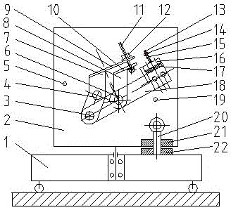
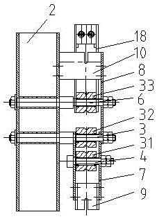
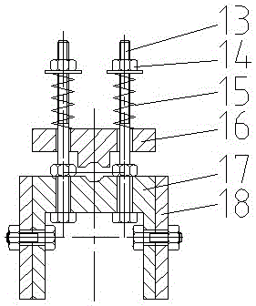
[0018] A floating pipe tying steel wire device used in the manufacturing process of floating pipes, including a trolley 1 and a turret 2, the trolley 1 can move on the guide rail, and the turret 2 is installed on the trolley 1 and can rotate. An indexing plate 22 with holes is installed on the upper surface of 1, and a fixed plate 21 with holes is welded on the lower side of the turret 2. A pin 20 is inserted in the two holes, and a guide device is installed on one side of the turret 2. And pressing device, guiding device is connected with turret 2, and pressing device is connected with guiding device by connecting plate 18.

[0019] The guiding device consists of a left fixed shaft 3, a swing shaft 4, a left gear lever 5, a right fixed shaft 6, a small curved plate 7, a large curved plate 8, an upper slot plate 9, a lower slot plate 10, a swi...


PUM


Abstract

The invention relates to a manufacture device for floating pipes in the pipe manufacture field and particularly relates to a steel wire binding device for floating pipes. During prior floating pipe manufacture, spiral steel wires can be bound in the between inner and outer pipe walls of pipes uniformly in order to enable the pipes to have enough anti-pipe-bursting capacity, and accordingly, the pipe strength is improved. As the inner pipe walls are made of rubber, the tension to the steel wires during steel wire binding cannot be too large, otherwise, the inner pipe walls can be damaged; the tension to the steel wires cannot be too small, otherwise, the steel wires cannot be pressed on the outsides of the inner pipe walls uniformly, the pipe wall strength is uneven, and the pipe bursting danger can be increased. The steel wire binding device is reasonable in technology, low in production cost, high in yield, small in labor intensity of workers and capable of well achieving continuous mechanized production during steel wire binding, convenient to operation and controllable in steel wire tension.

Description

technical field [0001] The invention relates to a floating pipe manufacturing equipment in the pipeline manufacturing field, in particular to a floating pipe wire binding device for binding steel wires on the surface of the floating pipe. Background technique [0002] In the manufacturing process of the existing floating pipe, in order to make the pipe have sufficient ability to prevent pipe explosion, helical steel wires can be evenly tied in the middle of the inner and outer pipe walls of the pipe to increase the strength of the pipe. Since the inner pipe wall is made of rubber, the pulling force on the steel wire cannot be too large when tying the steel wire, otherwise the inner pipe wall will be damaged, and the pulling force should not be too small, otherwise the steel wire will not be evenly pressed on the outer side of the inner pipe wall. This will make the strength of the tube wall uneven and also increase the risk of a tube burst. [0003] In view of this, it is o...

Claims


Application Information

Patent Timeline
Patent Type & Authority Patents(China)
IPC IPC(8): B21F3/02
Inventor 陈兴和陈骁凌素芳朱睿宿鹰杨琥
Owner ZHENJIANG COLLEGE
Why Eureka
Try Eureka