
Full-automatic washing machine foam removing system
A fully automatic washing machine and defoaming technology, applied to other washing machines, washing machine control devices, washing devices, etc., can solve the problems of increasing the resistance of the inner tub, increasing the energy consumption of dehydration, and increasing the moisture content of clothes, so as to protect the motor. Effect
- Summary
- Abstract
- Description
- Claims
- Application Information
AI Technical Summary
Problems solved by technology
Method used
Image

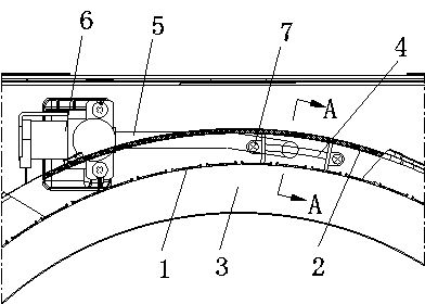
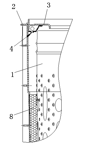
Examples
Embodiment Construction
[0011] The present invention will be further described below in conjunction with accompanying drawing:
[0012] Such as figure 1 , figure 2 A full-automatic washing machine defoaming system shown includes an inner barrel 1 and an outer barrel 2, an outer barrel cover 3 is arranged above the outer barrel 2, and a nozzle 4 is arranged on the outer barrel cover 3, and the nozzle 4 communicates with the water inlet through the water inlet pipeline 5. The water valve 6 is connected, at least one nozzle 4 is provided, and the injection direction of the nozzle 4 points between the inner tub 1 and the outer tub 2, and the water inlet valve 6 is connected with the controller.
[0013] Further, a plurality of nozzles 4 are evenly arranged along the circumferential direction of the outer barrel cover 3, and the water inlet valve 6 is provided with a plurality of water outlets, and the plurality of nozzles are connected to the water inlet valve through a plurality of water inlet pipelin...
PUM
 Abstract
Description
Claims
Application Information