Control rod driving mechanism and method

A driving mechanism and control mechanism technology, applied in the control of nuclear reactions, nuclear power generation, climate sustainability, etc., can solve the problem of inability to directly use manual methods, and achieve the effects of simple structure, high reliability and low manufacturing cost

Active Publication Date: 2014-02-05
SICHUAN HUADU NUCLEAR EQUIP MFR
View PDF9 Cites 11 Cited by
  • Summary
  • Abstract
  • Description
  • Claims
  • Application Information

AI Technical Summary

Problems solved by technology

For safety reasons, the insertion, extraction, and refueling of control rods cannot be performed manually
For the sake of work efficiency, it is not a good choice to use manual methods to insert, extract, and refuel the control rods.

Method used


Image

  • Control rod driving mechanism and method
  • Control rod driving mechanism and method
  • Control rod driving mechanism and method

Examples


Embodiment 1

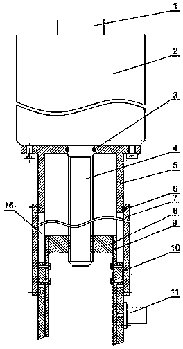
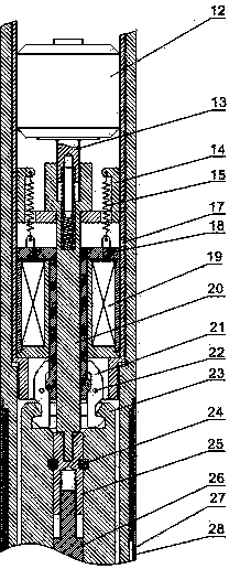
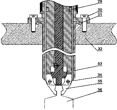
[0056] Such as Figure 1~Figure 3 As shown, the control rod drive mechanism includes the following components: a fixed outer cylinder 5; a movable inner cylinder 9 that is movably arranged in the fixed outer cylinder 5; a first driving device that drives the movable inner cylinder 9 to move up and down; The drive shaft 23 in the fixed outer cylinder 5 and positioned at the bottom of the movable inner cylinder 9; the hook 21 which is arranged at the bottom of the movable inner cylinder 9 and can clamp the top of the drive shaft 23; the first opening and closing of the driving hook 21 The control mechanism; the handle 35 arranged at the bottom end of the drive shaft 23; the second control mechanism for driving the handle 35 to open and close.

[0057] The working principle of this embodiment is as follows:

[0058] Moving steps: the second control mechanism drives the gripper 35 to grasp the control rod operating head 36, the first control mechanism drives the claw 21 to open a...

Embodiment 2

[0065] Such as Figure 1~3 As shown, on the basis of Embodiment 1, this embodiment discloses the first driving device with the following structure in order to simplify the structure and improve the reliability of the first driving device.

[0066] The first driving device includes a main driving motor 2, and the main driving motor 2 is fixed on the top of the fixed outer cylinder 5; the first driving device also includes a screw mandrel 4 connected to the output end of the main driving motor 2, The nut 8 that is arranged on the top of the movable inner cylinder 9, the threaded screw 4 and the nut 8 fit together.

[0067] In this embodiment, the cooperation of the screw mandrel 4 and the nut 8 is used to realize the up and down movement of the movable inner cylinder 9 . The cooperation between the screw rod 4 and the nut 8 is relatively reliable, the structure is simple, and the manufacturing cost is low.

Embodiment 3

[0069] Such as Figure 1~Figure 3 As shown, this embodiment provides a first control mechanism with more reliable control on the basis of any one of the above embodiments.

[0070] The upper inner surface of the hook 21 is provided with an upper trapezoidal groove, the lower inner surface of the hook 21 is provided with a lower trapezoidal groove, and the hook 21 is rotated and fixed by the hook pin 22. At the bottom end, the top of the drive shaft 23 is provided with a card slot matching with the lower end of the hook claw 21;

[0071] The first control mechanism includes a tension spring bracket 14 fixed in the movable inner cylinder 9, an electromagnetic coil 19 fixed in the movable inner cylinder 9, and arranged between the tension spring bracket 14 and the electromagnetic coil 19 The electromagnetic armature 18 is connected to the top of the electromagnetic armature 18 and the extension spring 15 of the extension spring bracket 14, and the bottom of the electromagnetic a...


PUM


Abstract

The invention discloses a control rod driving mechanism. The control rod driving mechanism comprises a fixed outer cylinder, a movable inner cylinder, a first driving device, a driving shaft, a hook claw, a first control mechanism, a hand grab and a second control mechanism, wherein the movable inner cylinder is movably arranged in the fixed outer cylinder; the first driving device is used for driving the movable inner cylinder to move up and down; the driving shaft is arranged in the fixed outer cylinder and is positioned below the movable inner cylinder; the hook claw is arranged at the bottom end of the movable inner cylinder and can tightly clamp the top end of the driving shaft; the first control mechanism is used for driving the hook claw to be opened and closed; the hand grab is arranged at the bottom end of the driving shaft; the second control mechanism is used for driving the hand grab to be opened and closed. The invention also discloses a control rod driving method. The control rod driving mechanism and method have the advantages of simple structure, low manufacturing difficulty and reliable motion.

Description

technical field [0001] The invention relates to the field of nuclear industry, in particular to a control rod driving mechanism and a control rod driving method. Background technique [0002] During the operation of the reactor, it is necessary to control the work of the control rods, which involves the insertion, withdrawal and refueling of the control rods. For the sake of safety, the work of inserting, withdrawing and refueling of the control rods cannot be directly carried out manually. For the sake of work efficiency, it is not a good choice to use manual methods to insert, extract, and refuel the control rods. Therefore, there is a need for a device capable of inserting, withdrawing, refueling and other operations on the control rod. Contents of the invention [0003] The purpose of the present invention is to overcome the disadvantages of the prior art and provide a control rod driving mechanism with simple structure, low manufacturing difficulty and reliable oper...

Claims


Application Information

Patent Timeline
Patent Type & Authority Applications(China)
IPC IPC(8): G21C7/10G21C7/14G21C7/16G21C17/12
CPCY02E30/39Y02E30/30
Inventor 喻杰
Owner SICHUAN HUADU NUCLEAR EQUIP MFR
Why Eureka
Try Eureka