
Elastic wiring device

The technology of a wiring device and an elastic wire clamp, which is applied in the electrical field, can solve problems such as the quality of wire fastening cannot be guaranteed, the fastening operation process is inconvenient, and the personal safety of operators cannot be guaranteed, etc.

Active Publication Date: 2014-02-05
SHANGHAI MUNICIPAL ELECTRIC POWER CO +1
View PDF14 Cites 1 Cited by
  • Summary
  • Abstract
  • Description
  • Claims
  • Application Information

AI Technical Summary

Problems solved by technology

To compress the wires, the operator must hold a wrench in each hand, and tighten the nuts and bolts at the same time to compress the wires; and for the operators who perform live operations on the poles, it is not necessary to operate live with both hands at close range. Realistic; and when carrying out live work, the operator must use two sets of insulated fastening tools at the same time to carry out the fastening operation of the bolts. The fastening quality is not good, which leads to the connection wire heating at the connection point, the serious oxidation of the wire and the failure of the connection quality, and the personal safety of the operator during the fastening bolt process cannot be guaranteed.
[0005] In addition, due to the connecting wire of Shanghai power supply line equipment, there is a 25mm 2 and 35mm 2 The wires of two specifications need to be equipped with crimping clamps of different specifications in order to adapt to wires of different diameters, which also increases the variety, specifications and quantity of spare parts, which is not conducive to reducing the quantity of spare parts and management costs.

Method used


Image

  • Elastic wiring device
  • Elastic wiring device
  • Elastic wiring device

Examples


Embodiment Construction

[0026] The present invention will be further described below in conjunction with the accompanying drawings.

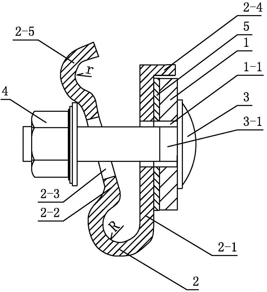
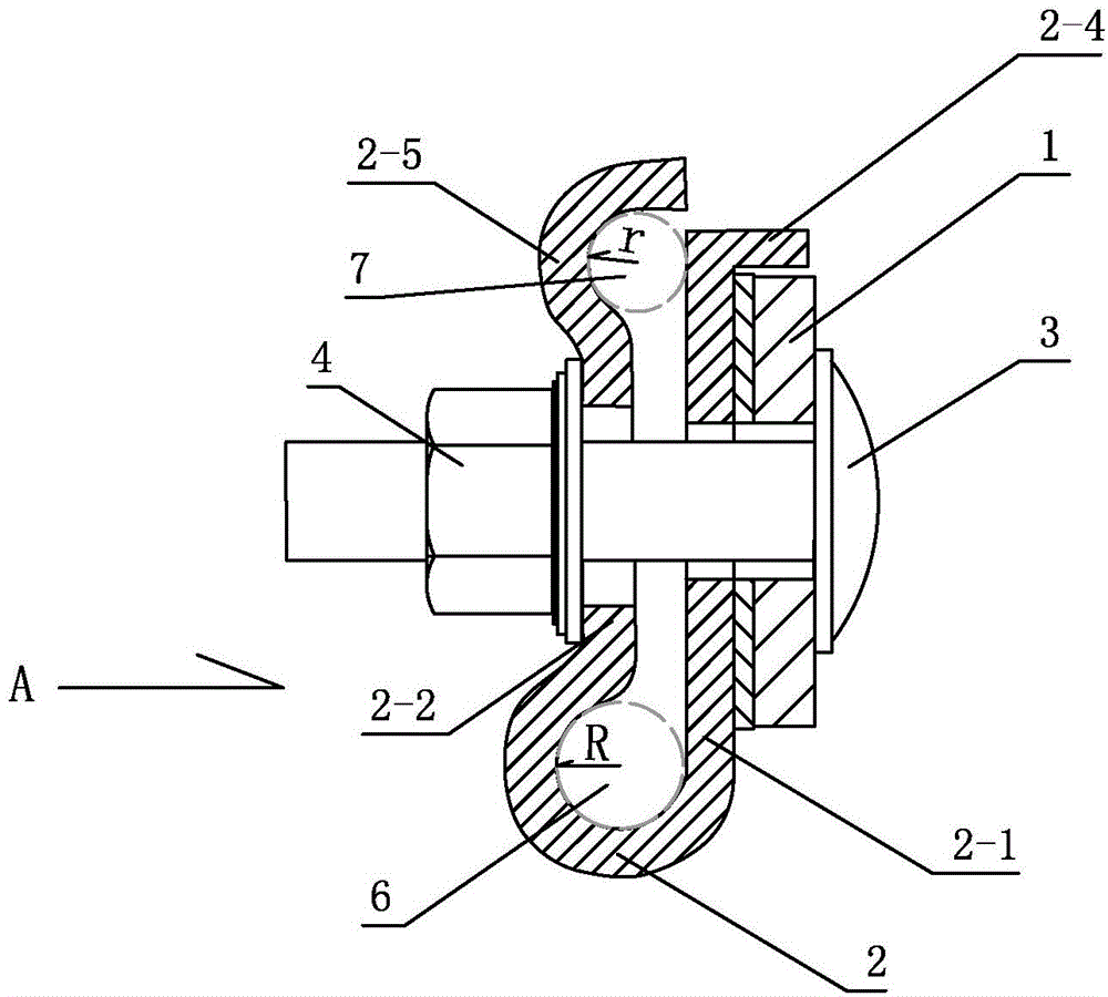
[0027] figure 2 Among them, this technical solution provides an elastic wiring device, which is composed of a C-shaped opening elastic wire clip, a half-round head square neck bolt and a hexagonal flange nut. Square neck bolts and hexagonal flange nuts are fastened on the bracket.

[0028] Among them, the C-shaped opening elastic clamp includes a C-shaped curved surface member 2 with a bending radius of R in the section. At the opening end of the C-shaped curved surface, first and second extended straight sides 2-1 and 2-2 are respectively provided. Bolt holes 2-3 are correspondingly provided on the first and second extended straight sides for passing through the half-round head square neck bolts.

[0029] At the end of the first extended straight side, a limit bending side 2-4 is arranged.

[0030] On the bracket 1, a regular polygonal hole 1-1 is opened.

[0031...


PUM


Abstract

The invention discloses an elastic wiring device and belongs to the field of electricity. The elastic wiring device comprises a C-shaped open elastic cable clamp, a cup head square neck bolt and a hexagonal flange-surface nut. The C-shaped open elastic cable clamp comprises a C-shaped curved-surface component with the bending radius of the section being R, a first lengthened straight edge and a second lengthened straight edge are arranged at the open end of the C-shaped curved surface and provided with bolt holes correspondingly, and a limiting bent edge is arranged at the tail end of the first lengthened straight edge. A support is provided with a regular polygonal hole, a haft of the cup head square neck bolt is arranged in the regular polygonal hole, and the C-shaped open elastic cable clamp is arranged on the other side of the support. The cup head square neck bolt is fastened and connected to the hexagonal flange-surface nut after penetrating through the bolt holes in the first lengthened straight edge and the second lengthened straight edge. When the elastic wiring device is fastened, a wire can be fastened fast through one box spanner, equipment live line connection operation can be carried out on an electric pole conveniently, and the elastic wiring device can adapt to connection of two wires of different wire diameters at the same time and guarantee personal safety of operation staff in the operation process.

Description

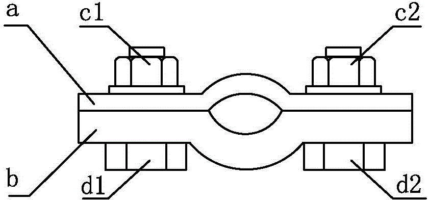
technical field [0001] The invention belongs to the field of electricity, and in particular relates to a connecting device for conveniently connecting wires of two specifications. Background technique [0002] With the increasing development of urbanization and power supply construction, higher and higher requirements are put forward for the production, safety and maintenance of power supply lines and related equipment. [0003] The wiring operation of power supply lines and their equipment is closely related to the maintenance and safety of line equipment. [0004] In the past, for the wiring of the equipment on the concrete pole of the power supply line, the crimping clamp (commonly known as the wiring clamp in the industry, generally used for the connection of single or two wires, such as figure 1 shown), which uses two upper and lower pressure plates (indicated by a, b in the figure), at least two sets of hexagonal bolts (d1, d2), two sets of hexagonal nuts (c1, c2), an...

Claims


Application Information

Patent Timeline
Patent Type & Authority Applications(China)
IPC IPC(8): H01R11/00H01R11/05H01R4/44
Inventor 庞仲豪陆茂鑫王召夏季海华秦岭张宇贲飞
Owner SHANGHAI MUNICIPAL ELECTRIC POWER CO
Learn More