
Overwater solar power station

A technology for solar panels and power stations, which is applied in the field of solar energy and can solve problems such as weak performance

Active Publication Date: 2014-02-05
YINGLI GRP +1
View PDF5 Cites 7 Cited by
  • Summary
  • Abstract
  • Description
  • Claims
  • Application Information

AI Technical Summary

Problems solved by technology

[0004] The present invention aims to provide a solar power station on water to solve the problem of weak performance of the solar power station on water in the prior art against the impact of water flow

Method used


Image

  • Overwater solar power station

Examples


Embodiment Construction

[0020] It should be noted that, in the case of no conflict, the embodiments in the present application and the features in the embodiments can be combined with each other. The present invention will be described in detail below with reference to the accompanying drawings and examples.

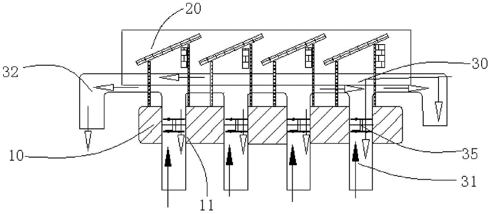
[0021] Such as figure 1 As shown, the floating solar power station of this embodiment includes a base 10 and a solar panel 20 arranged on the base 10 . The base 10 is provided with an overflow hole 11 passing through the base 10 . A first end of the flow hole 11 communicates with the bottom surface of the base 10 .

[0022] Applying the technical solution of this embodiment, the floating solar power station includes a base 10 and a solar panel 20 . The solar panel 20 is disposed on the base 10 . The base 10 is provided with an overflow hole 11 passing through the base 10 , and a first end of the overflow hole 11 communicates with the bottom surface of the base 10 . Since the floating solar...


PUM


Abstract

The invention provides an overwater solar power station which comprises a base (10) and a solar cell panel (20) arranged on the base (10). Overflowing holes (11) penetrating through the base (10) are formed in the base (10), and the first ends of the overflowing holes (11) are communicated with the bottom face of the base (10). Through the technical scheme, the problem that an overwater solar power station in the prior art is poor in flow impact resisting performance is effectively solved.

Description

technical field [0001] The invention relates to the technical field of solar energy, in particular to a water solar power station. Background technique [0002] With the depletion of non-renewable resources such as oil and gas, human beings pay more and more attention to the development and application of renewable energy. As a device that converts solar light into electrical energy through the photovoltaic effect, solar cells are environmentally friendly and inexhaustible. [0003] At present, the application range of solar power stations is becoming wider and wider. For areas with sufficient sunshine but limited land area, floating solar power generation systems have become a new choice. Solar power plants floating on the water are often affected by harsh environments, and the impact of water flow is very harmful to solar power plants. However, the water solar power stations in the prior art are relatively weak in resisting the impact of water flow. Contents of the inv...

Claims


Application Information

Patent Timeline
IPC IPC(8): H02S10/00H02S10/10H02S20/00
CPCY02E10/50
Inventor 倪健雄韩帅刘克铭蒋京娜权倩倩荣丹丹
Owner YINGLI GRP
Learn More