Lamp power control circuit

A technology for controlling circuit and lamp power, applied in electric light sources, electrical components, gas discharge lamps, etc., can solve the problems of iron core heating energy, large short-circuit current, waste and other problems, and achieve the effect of saving electricity and protecting bulbs

Inactive Publication Date: 2014-02-05
殷红
View PDF3 Cites 0 Cited by
  • Summary
  • Abstract
  • Description
  • Claims
  • Application Information

AI Technical Summary

Problems solved by technology

[0004] Now there is a method to adjust the power by changing the inductance of the ballast, which is to add an auxiliary winding to the inductance ballast, and short-circuit the auxiliary winding to saturate part of the iron core magnetic circuit of the inductance ballast to change the inductance ballast. The inductance of the device can be adjusted to adjust the current and then the power of the lamp. The structure of the magnetic ballast is complex. When the secondary winding is short-circuited, the short-circuit current is very large, causing the iron core to heat up and waste energy. Therefore, this method is difficult to be accepted by the market.

Method used


Image

  • Lamp power control circuit
  • Lamp power control circuit
  • Lamp power control circuit

Examples


Embodiment 1

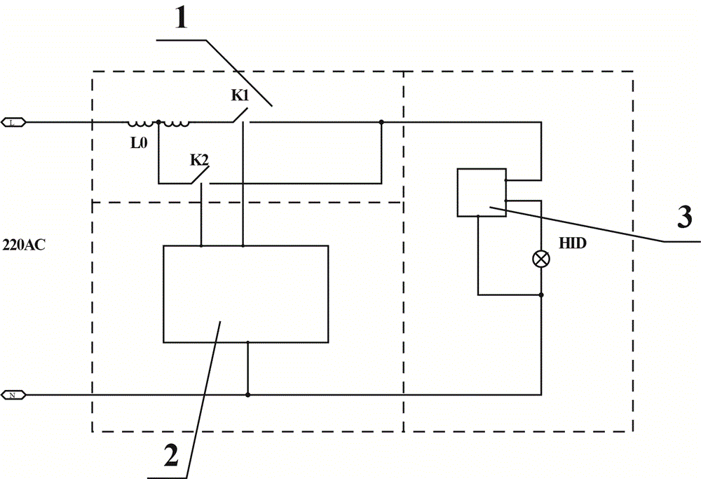
[0021] like figure 1 , the mains 220 volt AC live wire L is connected to the left end of the magnetic ballast L0, the right end of the magnetic ballast L0 is connected to the left end of the first switching tube K1, and the middle tap of the magnetic ballast L0 is connected to the left end of the second switching tube K2, The right end of the first switching tube K1 and the right end of the second switching tube K2 are connected to each other and then connected to the input end of the starter 3, the output end of the starter 3 is connected to one end of the bulb HID, and the other end of the bulb HID is connected to the mains 220 volts AC zero Line N.

[0022] The first switching tube K1 and the second switching tube K2 are respectively connected to the controller 2 .

[0023] The starter 3 and the controller 2 are also respectively connected to the neutral line N of the 220-volt alternating current of the commercial power.

Embodiment 2

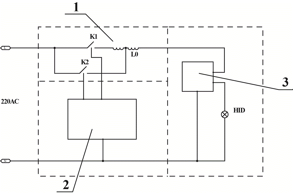
[0025] like figure 2 , the left end of the magnetic ballast L0 is connected to the right end of the first switching tube K1, the middle tap of the magnetic ballast L0 is connected to the right end of the second switching tube K2, and the left end of the first switching tube K1 is connected to the left end of the second switching tube K2. After connection, connect to mains 220V AC live wire L. The right end of the magnetic ballast L0 is connected to the input end of the starter 3, the output end of the starter 3 is connected to one end of the bulb HID, and the other end of the bulb HID is connected to the mains 220V AC neutral line N.

[0026] The first switching tube K1 and the second switching tube K2 are respectively connected to the controller 2 .

[0027] The starter 3 and the controller 2 are also respectively connected to the neutral line N of the 220-volt alternating current of the commercial power.

Embodiment 3

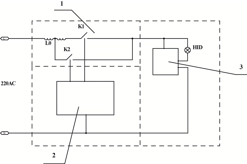
[0029] like image 3 , the mains 220 volt AC live wire L is connected to the left end of the magnetic ballast L0, the right end of the magnetic ballast L0 is connected to the left end of the first switching tube K1, and the middle tap of the magnetic ballast L0 is connected to the left end of the second switching tube K2, The right end of the first switching tube K1 and the right end of the second switching tube K2 are connected to each other and then respectively connected to one end of the starter 3 and one end of the bulb HID, and the other end of the bulb HID is connected to the other end of the starter 3 .

[0030] The first switching tube K1 and the second switching tube K2 are respectively connected to the controller 2 .

[0031] The starter 3 and the controller 2 are also respectively connected to the neutral line N of the 220-volt alternating current of the commercial power.


PUM


Abstract

The invention discloses a lamp power control circuit. One end of an inductive ballast (L0) of a current regulating circuit (1) is connected with one end of a first switching tube (K1). A center tap is connected with one end of a second switching tube (K2). The other end of the second switching tube (K2) is connected with the other end of the first switching tube (K1). A lamp starting circuit is further comprised, wherein the lamp starting circuit is connected on the front end or the rear end of the current regulating circuit (1) and composed of a lamp bulb (HID) and a starter(3) for starting the lamp bulb (HID). A controller (2) is further comprised, wherein the controller (2) is connected with the first switching tube (K1) and the second switching tube (K2) separately. By regulating the time of the current flowing from the inductive ballast center tap, the average value of the current flowing through the lamp can be regulated, so that the purpose of lamp power stepless regulation can be realized. The controller is used to calculate the lamp power by measuring the lamp voltage and the lamp current, and perform closed-loop regulation according to the lamp power, so that the purpose of constant power control can be realized.

Description

[0001] technical field [0002] The invention relates to a lamp power control circuit. Background technique [0003] Current HID lamps generally use magnetic ballasts to stabilize the current, but magnetic ballasts cannot continuously and steplessly adjust the lamp power, which is very inconvenient in use, such as when it is necessary to adjust the light. For another example, in the existing magnetic ballast circuit, when the voltage changes, the lamp power changes accordingly, and when the grid voltage rises, the lamp power increases, resulting in power waste and reduced bulb life. Therefore, there is an urgent need for a stepless power adjustment method in the market, so that the magnetic ballast can also continuously adjust the light according to the needs, and realize constant control of the lamp power in the magnetic ballast circuit. [0004] Now there is a method to adjust the power by changing the inductance of the ballast, which is to add an auxiliary winding to the...

Claims


Application Information

Patent Timeline
Patent Type & Authority Applications(China)
IPC IPC(8): H05B41/36
CPCY02B20/204Y02B20/00
Inventor 殷红
Owner 殷红
Why Eureka
Try Eureka