Pin pulling device

A technology of guide parts and guide holes, which is applied in the direction of hand-held tools and manufacturing tools, can solve problems such as difficult pin extraction, and achieve the effect of solving difficult pin extraction, simple operation, and convenient clamping

Active Publication Date: 2015-05-13
GUANGXI YUCHAI MASCH CO LTD
View PDF6 Cites 0 Cited by
  • Summary
  • Abstract
  • Description
  • Claims
  • Application Information

AI Technical Summary

Problems solved by technology

[0005] The purpose of the present invention is to overcome the defects in the above-mentioned prior art, and provide a device for pulling out pins, which solves the problem of difficulty in pulling out pins, is simple to operate, and does not damage the pin itself

Method used


Image

  • Pin pulling device
  • Pin pulling device
  • Pin pulling device

Examples


Embodiment Construction

[0020] The specific embodiments of the present invention will be described in detail below in conjunction with the accompanying drawings, but it should be understood that the protection scope of the present invention is not limited by the specific embodiments.

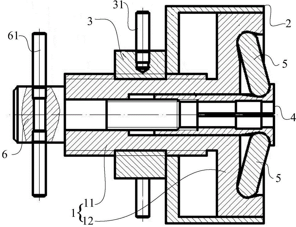
[0021] The pin pulling device of the present invention is mainly designed for the difficulty in extracting the existing pins, by designing the chuck to clamp the exposed part of the pin, and then driving the chuck to move through the threaded sleeve to take out the pin. The device can be operated on an in-situ production line without being limited by time and place, and the device is easy to operate and has high efficiency. In addition, the device will not damage the pins and save costs.

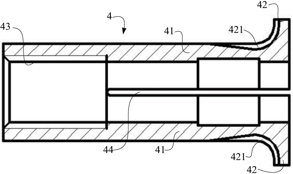
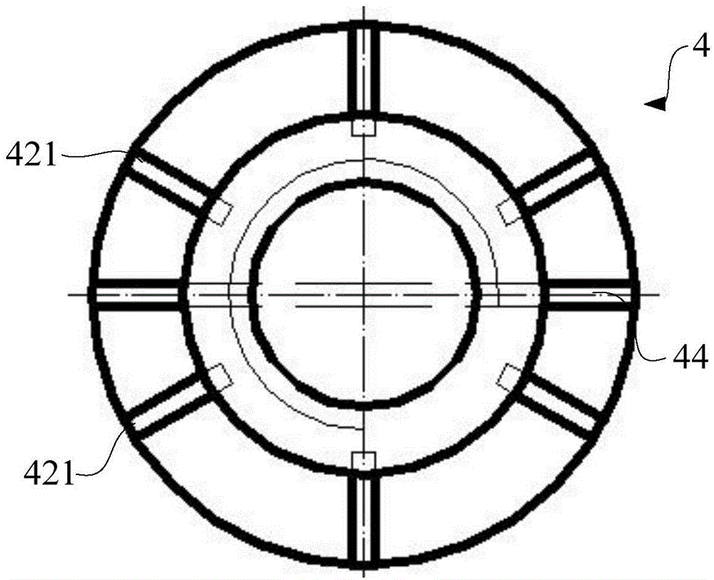
[0022] like figure 1 As shown, the pin pulling device of the present invention includes a main body 1, a support sleeve 2, a threaded sleeve 3, a chuck 4, a fan piece 5 and a rotating head 6. The main body 1 specifically includes an ...


PUM


Abstract

The invention discloses a pin pulling device, which comprises a body, and specifically comprises a guide part and a support part which are integrally molded, a support sleeve, a threaded sleeve, a chuck, fan blades, and a rotating head, wherein a support groove is formed in the support part, and the body is arranged in the support sleeve and slides relative to the support sleeve; the threaded sleeve is arranged on the guide part, and one end of the threaded sleeve is propped against the end face of the support sleeve; when the threaded sleeve is rotated, the body and the support sleeve oppositely move; the chuck is arranged in the guide part and is provided with two jaws, and the end heads of the two jaws are outwards provided with support blocks respectively; the fan blades are arranged between the support groove and the support blocks, and the jaws are extruded by the fan blades to move inward to clamp a pin to be pulled; the rotating head is in threaded connection with the chuck and drives the chuck to move through threads so that the pin is pulled out. The device is simple and quick to operate, and does not damage the pin.

Description

technical field [0001] The invention relates to the field of mechanical assembly, in particular to a pin pulling device. Background technique [0002] In the field of mechanical assembly, pins are mainly used for assembly positioning and can also be used as connectors. For example, cylindrical pins are commonly used as connectors in the field of mechanical assembly, and most cylindrical pins are installed on parts through interference fit. Generally, the exposed part of cylindrical pins is often very short (4-5mm). The straight pin itself is very smooth, and there is no point to apply force to. At this time, it is very difficult to pull out the straight pin. [0003] At present, the general method is to weld a bolt on the head of the cylindrical pin under the condition of protecting the parts well, and then pull out the bolt to achieve the purpose of removing the cylindrical pin. [0004] However, when using the above-mentioned method to extract the cylindrical pin, firstl...

Claims


Application Information

Patent Timeline
Patent Type & Authority Patents(China)
IPC IPC(8): B25B27/02
CPCB25B27/023B25B27/08
Inventor 王俊蛟朱岩郑文康曾黎
Owner GUANGXI YUCHAI MASCH CO LTD
Why Eureka
Try Eureka