Method for manufacturing porous stamp, porous stamp, and apparatus for manufacturing porous stamp

A manufacturing method and technology of a manufacturing device are applied in the field of manufacturing devices of porous stamps, which can solve the problems of long ink impregnation time, slow impregnation time, offset of stamp imprint, etc. , The effect of convenient ink impregnation time

Active Publication Date: 2017-09-15
SHACHIHATA IND
View PDF2 Cites 0 Cited by
  • Summary
  • Abstract
  • Description
  • Claims
  • Application Information

AI Technical Summary

Problems solved by technology

Then, the stamp surface formed based on the porous stamp material also deviates from the designed position relative to the rootstock. Therefore, when the user stamps based on the rootstock, there is a bad situation that the stamped imprint is shifted.
[0017] In addition, in the method of manufacturing a liquid-impregnated stamp disclosed in Patent Document 3, since the porous stamp material on which the stamp surface is formed is assembled into a box, there is a problem that the stamp surface is shifted relative to the box.
[0018] In addition, there is a problem that the ink impregnation time is long.
[0019] That is, in the configuration of Patent Document 2, since the ink retention portion as the bearing member is an essential configuration, when the ink is impregnated, the ink is sequentially injected into the stamp material from the ink retention portion that is not impregnated with ink, and the ink impregnation time is correspondingly reduced. slow down

Method used


Image

  • Method for manufacturing porous stamp, porous stamp, and apparatus for manufacturing porous stamp
  • Method for manufacturing porous stamp, porous stamp, and apparatus for manufacturing porous stamp
  • Method for manufacturing porous stamp, porous stamp, and apparatus for manufacturing porous stamp

Examples


Embodiment Construction

[0064] Hereinafter, a first embodiment of the method for manufacturing a porous stamp, the porous stamp, and the apparatus for manufacturing a porous stamp of the present invention will be described with reference to the drawings.

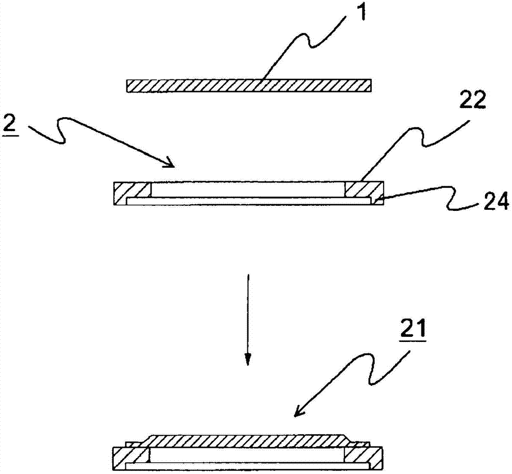
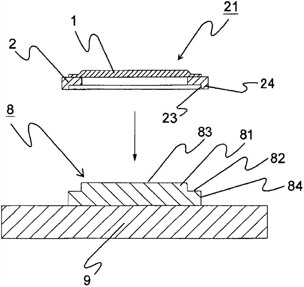
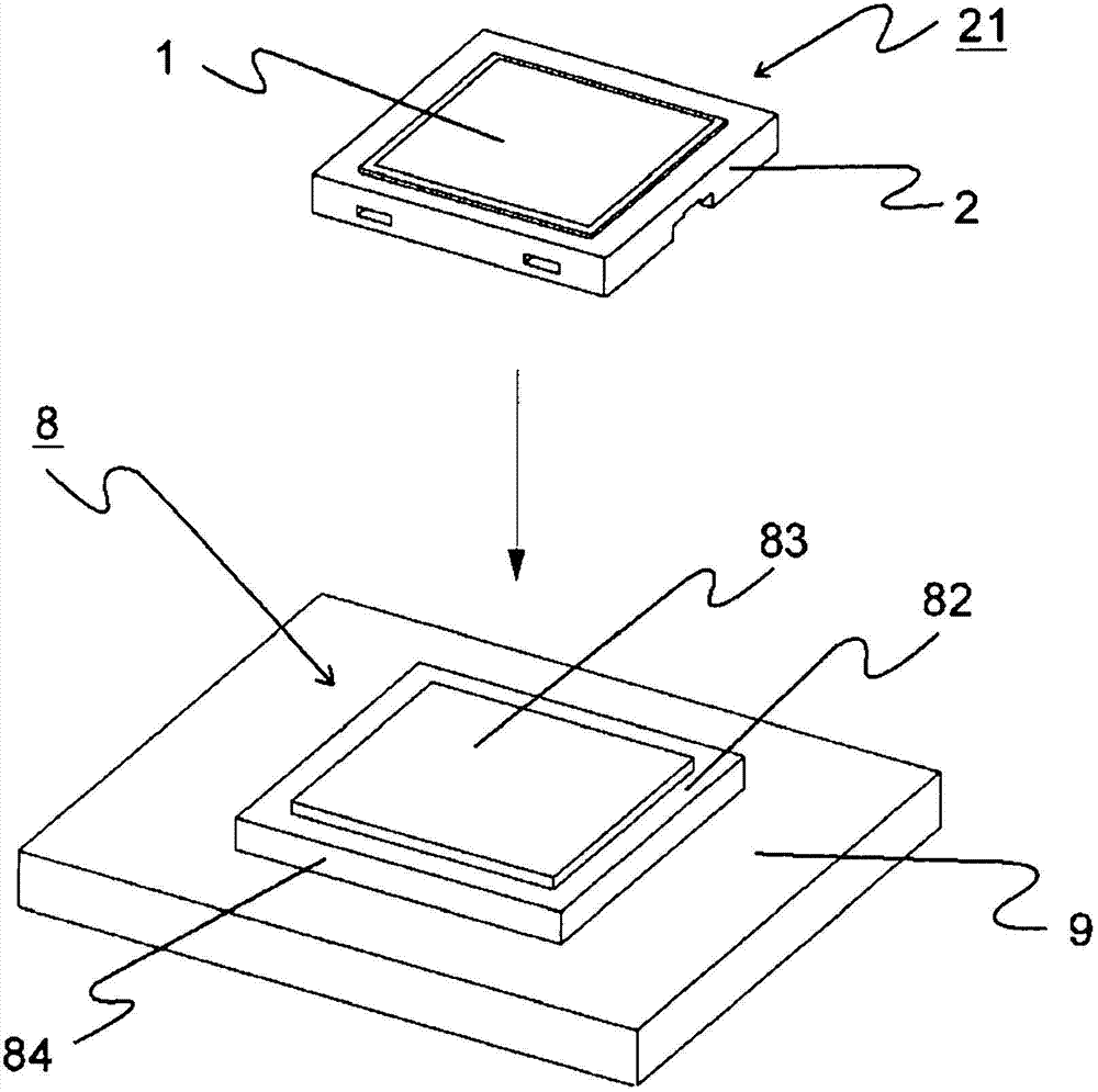
[0065] The porous stamp in this example includes: Figure 1~Figure 6 A porous stamp material 1 made of thermoplastic resin as shown; a frame 2 to which the porous stamp material 1 is hermetically bonded; and a holder 4 holding an ink absorbing body 3 impregnated with ink.

[0066] Here, the seal surface side of the porous stamp is referred to as "front" and "front", and the opposite side of the seal surface is referred to as "rear" and "back".

[0067] Such as figure 1 As shown, as the porous stamp material 1 made of thermoplastic resin, any material may be used as long as it is a porous body that can push a thermal head against the surface of the stamp material to heat and melt the surface. For example, the following materials are used as raw ma...


PUM

PropertyMeasurementUnit
thicknessaaaaaaaaaa
pore sizeaaaaaaaaaa
porosityaaaaaaaaaa

Abstract

The manufacturing method of the porous stamp of the present invention is characterized in that, comprises: the first step, the porous stamp material that is made of thermoplastic resin is hermetically bonded on the front end face of frame body, makes the frame body with stamp material; process, fixing the frame body with the stamp material on the carrier platform arranged opposite to the thermal head arranged on the seal surface forming device, making the back surface of the porous stamp material contact with the surface of the carrier platform; the third The step is to make the thermal head and the surface of the porous stamp material contact and move relative to each other through the resin film to form a stamp surface on the surface of the porous stamp material; After detaching the frame body with stamp material, hold the frame body with stamp material in a state where the back surface of the porous stamp material is in contact with the ink absorbing body impregnated with ink. There is the ink absorber on the bracket.

Description

technical field [0001] The present invention relates to a method for manufacturing a porous stamp, a porous stamp, and a device for manufacturing a porous stamp. Background technique [0002] A porous stamp is produced by forming a stamped portion (ink-permeable portion) and a non-stamp portion (ink-impermeable portion) having a stamp pattern on a porous stamp material. In order to form stamped portions (ink-permeable portions) and non-stamped portions (ink-impermeable portions), for example, a method using a thermal head is known. According to this method, the porous stamp material can be compressed (95~30% of the thickness of the porous stamp material) while passing between the thermal head equipped with a plurality of heating elements and the platen, According to the desired printed dot patterns such as characters or graphics, the heating drive of the heating element is selectively performed to form an ink-impermeable non-stamping part, and the part that is not heated by...

Claims


Application Information

Patent Timeline
Patent Type & Authority Patents(China)
IPC IPC(8): B41C1/14
CPCB41K1/00B41K1/38B41D7/00B41D7/04Y10T156/17B41K1/50
Inventor 阿部荣次内田成俊
Owner SHACHIHATA IND
Why Eureka
Try Eureka