
control device

A technology for manipulating devices and initial positions, applied in the direction of transmission control, components with teeth, belts/chains/gears, etc., which can solve problems such as increasing costs, depleting pawls, and sensitive to wear

Active Publication Date: 2017-06-09
SCHAEFFLER TECH AG & CO KG
View PDF1 Cites 0 Cited by
  • Summary
  • Abstract
  • Description
  • Claims
  • Application Information

AI Technical Summary

Problems solved by technology

However, this design is very complex with regard to the components used and the pawl is very wear-sensitive, which increases costs

Method used


Image

  • control device
  • control device
  • control device

Examples


Embodiment Construction

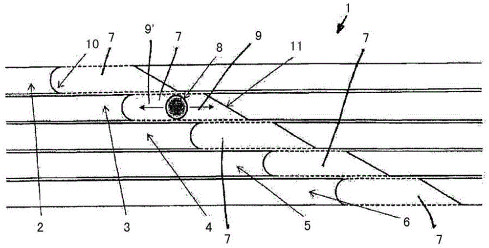
[0051] figure 1 An actuating device 1 is shown, which can be used in particular to actuate a transmission to select a transmission ratio and to engage and / or disengage the selected transmission ratio and / or to actuate a clutch to engage and / or disengage.

[0052] The actuating device 1 has a plurality of shift elements 2 , 3 , 4 , 5 , 6 which are arranged next to one another in a row. The shifting element 2 is adjacent to the shifting element 3 . The shifting element 3 is located next to the shifting elements 2 and 4, wherein the shifting element 2 is arranged on the opposite side of the shifting element 2, so that the shifting element 3 is thus arranged on the Between shift elements 2 and 4. The shifting element 4 is located between the shifting elements 3 and 5 and the shifting element 5 is located between the shifting elements 4 and 6 . The shifting element 6 is arranged adjacent to the shifting element 5 and is the last shifting element in the row, wherein the shifting...


PUM


Abstract

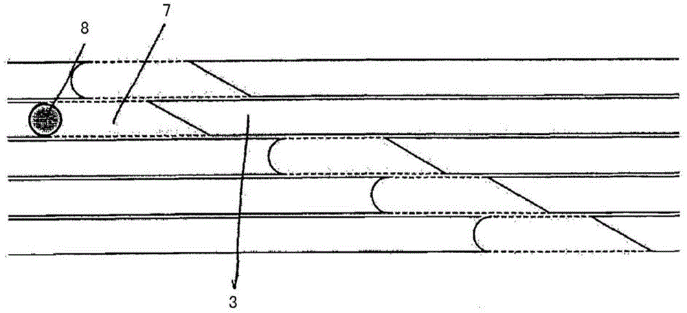
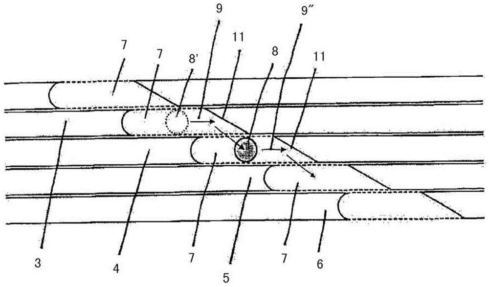
The actuating device (1) has a drive element with one pin (8) and switching elements (2-6) which are translational and / or rotationally displaceable. The switching element has a receiving portion (7) having a primary end portion and a secondary end portion for receiving the pin. The primary end portion is formed as stop region (10) for pressurizing and displacing of the switching element, and the secondary end portion is formed as ramp region (11) to change the pin to an adjacent switching element.

Description

technical field [0001] The invention relates to an actuating device, in particular for actuating a transmission to select a gear ratio and for engaging and disengaging the selected gear ratio and / or for actuating a clutch. Background technique [0002] In a vehicle transmission, the speed change between a transmission input shaft and a transmission output shaft is formed by a gear pair. Embodiments are disclosed here, for example, as spur gear transmissions. The shifting of the transmission takes place in this case via a shift mechanism in the transmission. In the case of a manual transmission, the shift mechanism is connected via a link or cable drive to a shift handle. In the case of an automatic transmission, the shifting mechanism is actuated by means of an actuating device having an actuator for selecting a transmission ratio stage and a detent for the transmission ratio stage. In or out actuator. [0003] In the case of the above-mentioned spur gear transmission, t...

Claims


Application Information

Patent Timeline
Patent Type & Authority Patents(China)
IPC IPC(8): F16H59/02F16H61/28
CPCF16H59/02F16H59/0278F16H61/32F16H2061/326F16H63/16F16H63/18F16H63/30
Inventor D·赫尔科默
Owner SCHAEFFLER TECH AG & CO KG
Learn More