Message forwarding method and device in data central network

A data center network and message forwarding technology, applied in the field of network communication, can solve problems such as low link bandwidth between chassis, affect traffic forwarding performance, and increase link load, so as to avoid increased link load between chassis, The effect of improving traffic forwarding performance

Active Publication Date: 2014-02-12
NEW H3C TECH CO LTD
View PDF5 Cites 4 Cited by
  • Summary
  • Abstract
  • Description
  • Claims
  • Application Information

AI Technical Summary

Problems solved by technology

It can be seen that when the local link between a Chassis and ToR in the IRF system fails, the traffic originally forwarded by the faulty link is transferred to the inter-chassis link between the Chassis. Although this can realize traffic forwarding, However, it will increase the load of the links between chassis, and, because the link bandwidth between chassis is relatively low, it will also affect the traffic forwarding performance

Method used


Image

  • Message forwarding method and device in data central network
  • Message forwarding method and device in data central network
  • Message forwarding method and device in data central network

Examples


Embodiment Construction

[0026] In order to make the object, technical solution and advantages of the present invention clearer, the present invention will be described in detail below in conjunction with the accompanying drawings and specific embodiments.

[0027] The method provided by the invention includes Figure 4 The flow shown:

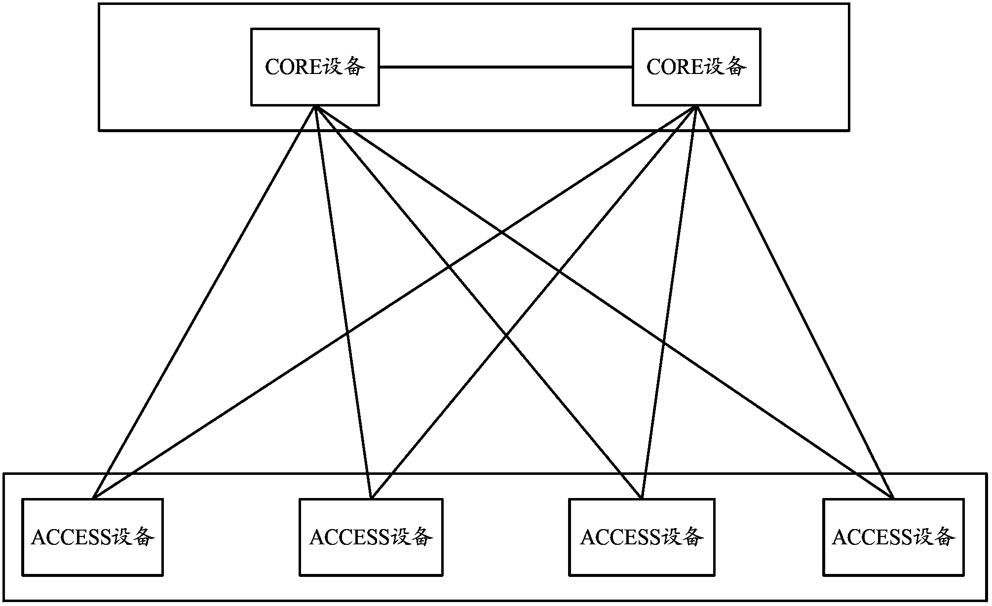
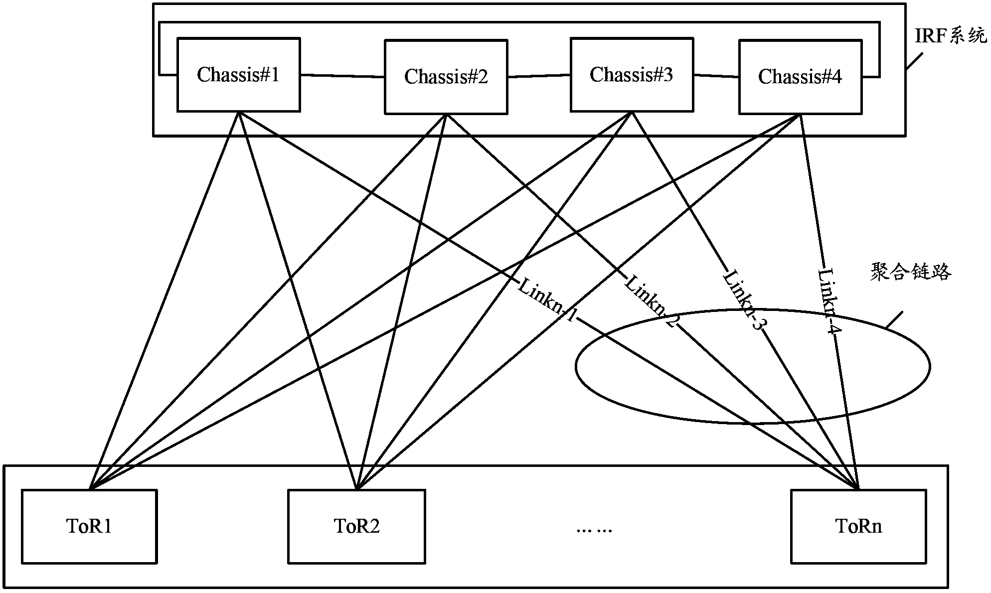
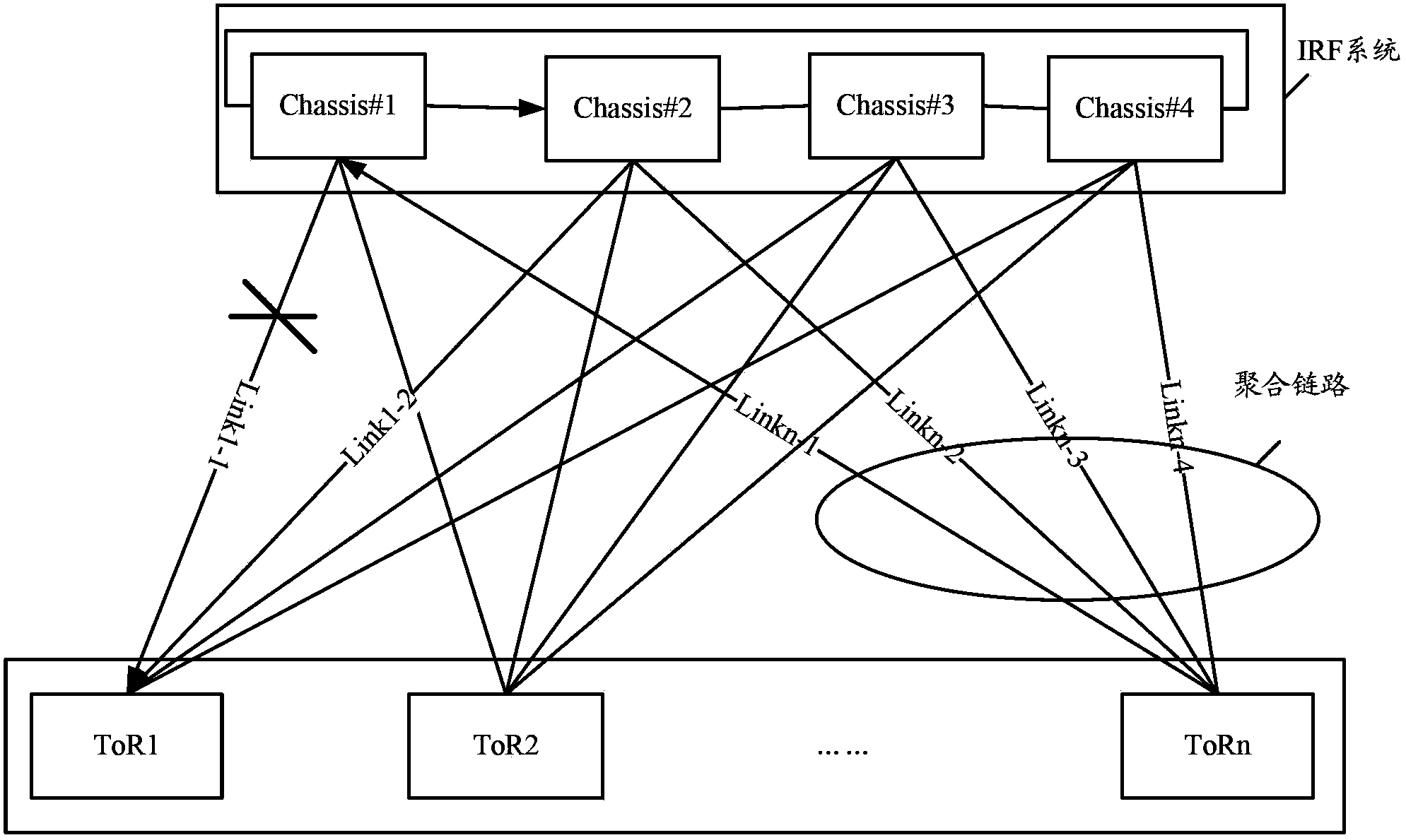
[0028] see Figure 4 , Figure 4 The flow chart of the method provided by the embodiment of the present invention. The method provided by the present invention is applied to a data center network, and the data center network includes at least: CORE devices and ACCESS devices, wherein all CORE devices form a stacking system through stacking, for example, CORE devices form an IRF system through IRF technology, and the data In the center network, the ACCESS device and the stacking system are connected through aggregated links. Here, the aggregated link between the ACCESS device and the stacking system is obtained by aggregating the links connecting the ACCESS device t...


PUM


Abstract

A data center network comprises CORE devices which are stacked to form a stack system and an ACCESS device. Information of connection between each CORE device in the stack system and its peer ACCESS devices is recorded. Upon determining a change in the information of connection between any CORE device and its peer ACCESS devices, said CORE device is labeled with a low-forwarding-capability identifier. When transmitting a message, the ACCESS device selects a CORE device other than the CORE device labeled with a low-forwarding-capability identifier to perform the message forwarding.

Description

technical field [0001] The present application relates to network communication technology, in particular to a message forwarding method and device in a data center network. Background technique [0002] At present, the data center network pursues 10 Gigabit non-blocking, loop-free, single-layer high-performance switching, and its typical networking is as follows: figure 1 As shown, it mainly includes: core (CORE) equipment and access (ACCESS) equipment. Among them, CORE equipment adopts high-performance switching structure to realize non-blocking switching, and ACCESS equipment adopts 10 Gigabit access to realize non-blocking uplink. [0003] In the data center network, in order to make full use of the forwarding capabilities of CORE devices, and realize load sharing and disaster backup between CORE devices, ACCESS devices and CORE devices are fully connected. However, this full connection method will generate loops, for example, the link connecting the same ACCESS device...

Claims


Application Information

Patent Timeline
Patent Type & Authority Applications(China)
IPC IPC(8): H04L12/891H04L47/41
CPCH04L45/245Y02D30/50H04L67/10
Inventor 常慧锋
Owner NEW H3C TECH CO LTD
Why Eureka
Try Eureka