Vibration damping method

a vibration damping and vibration technology, applied in the direction of shock absorbers, mechanical equipment, transportation and packaging, etc., can solve the problems of large load in the vehicle body and chassis, the damping force of such high piston speeds is too low to adequately dissipate the majority of the energy must be carried by the body structure, etc., to achieve the effect of dissipating the kinetic energy of the accelerated wheel, negative effect on driving comfor

Active Publication Date: 2014-06-24
BAYERISCHE MOTOREN WERKE AG
View PDF29 Cites 0 Cited by
  • Summary
  • Abstract
  • Description
  • Claims
  • Application Information

AI Technical Summary

Benefits of technology

[0007]Therefore, the object of the present invention is to provide a vibration damping method on a motor vehicle wheel suspension by means of a hydraulic vibration damper which prevents great loads on the vehicle body and chassis caused by very large vertical velocities of the wheel, e.g., when traveling over potholes or thresholds, and to do so without making any sacrifice in driving comfort or driving safety.
[0009]This has the advantage that the vibration damper prevents great loads on the body and chassis caused by very high vertical wheel speeds, e.g., when driving over an obstacle or a threshold, and does so without any sacrifice in terms of driving comfort or driving safety. Due to the highly progressive rise in damping force, especially beyond a piston speed of essentially 2 m / s, the vibration damper dissipates the energy of high vertical wheel speeds more rapidly and therefore prevents great loads on the body and chassis. The piston speed, beyond which a highly progressive rise in the damping force is to advantageously take place, is defined by the end of the comfort-relevant range in chassis design. According to the present consensus, the comfort-relevant range for passenger vehicles ends at a piston speed of approximately 2 m / s. However, this value may easily be 1 m / s to 4 m / s for certain desired vehicle properties due to differences in chassis design.
[0010]Through a suitable choice, design and construction of vibration damper valves or by otherwise influencing the hydraulic resistances in the vibration damper, it is possible to implement a characteristic which is generated by damping forces known from the state of the art in the piston speed range up to the end of the range that is relevant for comfort. Beyond this piston speed range, an extreme progression in the damper characteristic is induced to decelerate the accelerated masses to a greater extent. This ultimately produces reduced loads in the vehicle body and chassis owing to a lower residual energy in the end stop area and also permits lighter and less expensive designs of the vehicle body, chassis and the vehicle itself. This is especially advantageous for vehicles having a low range of the spring, e.g., for sporty vehicles with a low design. A longer vehicle lifetime under poor road conditions is achieved with less damage to the body structure.
[0012]It is even more advantageous if, following the steep, essentially linear course or following the highly progressive rise in the characteristic curve of the damping force as a function of piston speed, this characteristic curve then develops into an essentially linear course with a slight increase.

Problems solved by technology

However, this is not usually taken into account separately in chassis design.
At very high vertical wheel speeds much greater than 2 m / s, such as those occurring when driving over a pothole or a threshold, for example, great loads occur in the vehicle body and chassis in the end stop range due to accelerated unsprung masses.
In the usual vibration dampers, the damping force for such high piston speeds is too low to adequately dissipate the kinetic energy of the accelerated wheel, which means that most of the energy must be carried by the body structure.
This means that the structural components involved are massive and heavy and are therefore expensive to manufacture.
If the damping force of the vibration damper is increased on the whole, this has a negative effect on driving comfort at a vertical speed of less than 2 m / s.

Method used


Image

  • Vibration damping method
  • Vibration damping method

Examples


Embodiment Construction

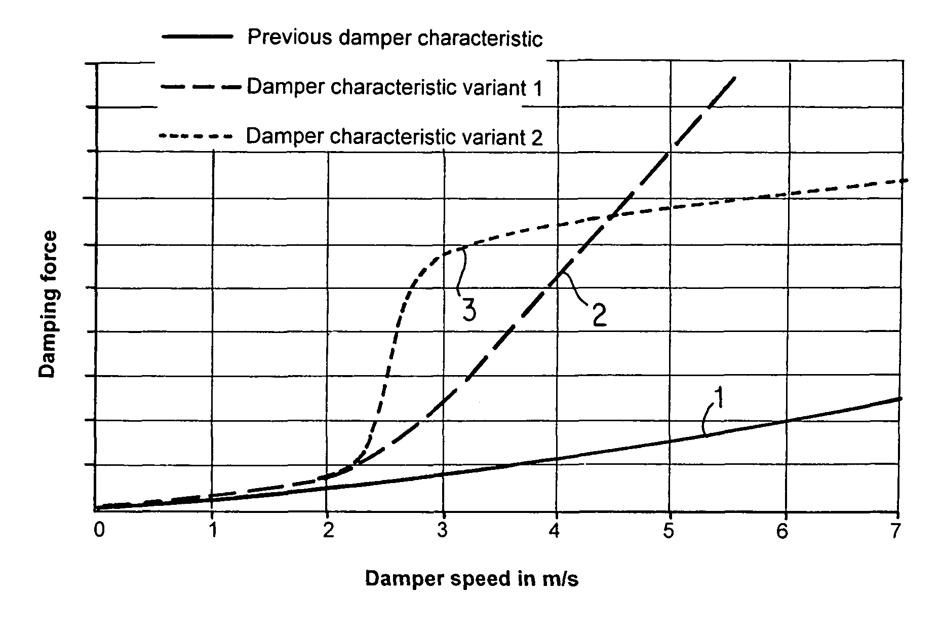
[0018]The first characteristic variant 1 of a damping force curve, represented by a continuous line in FIG. 1 as a function of piston speed is generated by a vibration damping method for a wheel suspension of a motor vehicle according to the state of the art. In damping force adjustment for motor vehicles, in particular for passenger vehicles, the damper characteristic is considered up to a piston speed of approximately 1-2 m / s from the standpoint of comfort and driving safety. As a rule, for a damping force characterization greater than 2 m / s, at most only a slightly progressive rise is obtained from the piston / valve combinations according to the state of the art. This is usually assumed in chassis design.

[0019]At very high vertical accelerations of the wheel greater than 2 m / s, such as those occurring, for example, in driving over an obstacle or a threshold, extremely high loads occur in the vehicle body and chassis due to the accelerated unsprung masses in the end stop range.

[002...


PUM


Abstract

A vibration damping method on a vehicle wheel suspension is provided in which, in a hydraulic vibration damper, the damping force increases highly progressively as a function of the piston speed, especially in the range of a piston speed of essentially 0 to 2 m / s, increasing at first slowly and essentially linearly and then especially beyond a piston speed of essentially 2 m / s increasing highly progressively.

Description

[0001]This application is a continuation application of International application PCT / EP2004 / 052337 filed Sep. 28, 2004 and claims the priority of German application No. 103 47 219.3, filed Oct. 10, 2003, the disclosure of which are expressly incorporated by reference herein.BACKGROUND AND SUMMARY OF THE INVENTION[0002]The invention relates to a method for damping vibration on a vehicle wheel suspension with a hydraulic vibration damper.[0003]German patent document DE 37 29 187 C2 describes a vibration damper with which the damping forces are adjustable for both directions of movement, indefinitely and independently, even during a spring deflection and recoil movement. Such a vibration damper has at least two working chambers separated by a piston with main overflow valves. A piston rod attached to the piston is guided through one of the working chambers. In addition to the main overflow valves, the working chambers are connected by an overflow opening that has an adjustable opening...

Claims


Application Information

Patent Timeline
Patent Type & Authority Patents(United States)
IPC IPC(8): F16F9/512B60G17/08F16F9/46
CPCF16F9/512B60G17/08B60G2400/202B60G2500/10
Inventor PFAFFENZELLER, PETERSTEIN, HEINRICHHAUKE, MIRCOSTROBL, HUBERT
Owner BAYERISCHE MOTOREN WERKE AG
Why Eureka
Try Eureka