Supercharge Your Innovation With Domain-Expert AI Agents!

Cold pilger mill feed-in mechanism

A technology of cold rolling mill and feeding mechanism, applied in metal rolling, metal rolling, metal processing equipment and other directions, can solve problems such as connection bolt breakage, and achieve easy adjustment, easy chain tension, and improved stress conditions. Effect

Inactive Publication Date: 2014-02-19
TAIYUAN HEAVY IND
View PDF5 Cites 0 Cited by
  • Summary
  • Abstract
  • Description
  • Claims
  • Application Information

AI Technical Summary

Problems solved by technology

[0004] The invention aims to improve the stressed state of the connecting block and solve the problem of broken connecting bolts

Method used


Image

  • Cold pilger mill feed-in mechanism
  • Cold pilger mill feed-in mechanism
  • Cold pilger mill feed-in mechanism

Examples


Embodiment Construction

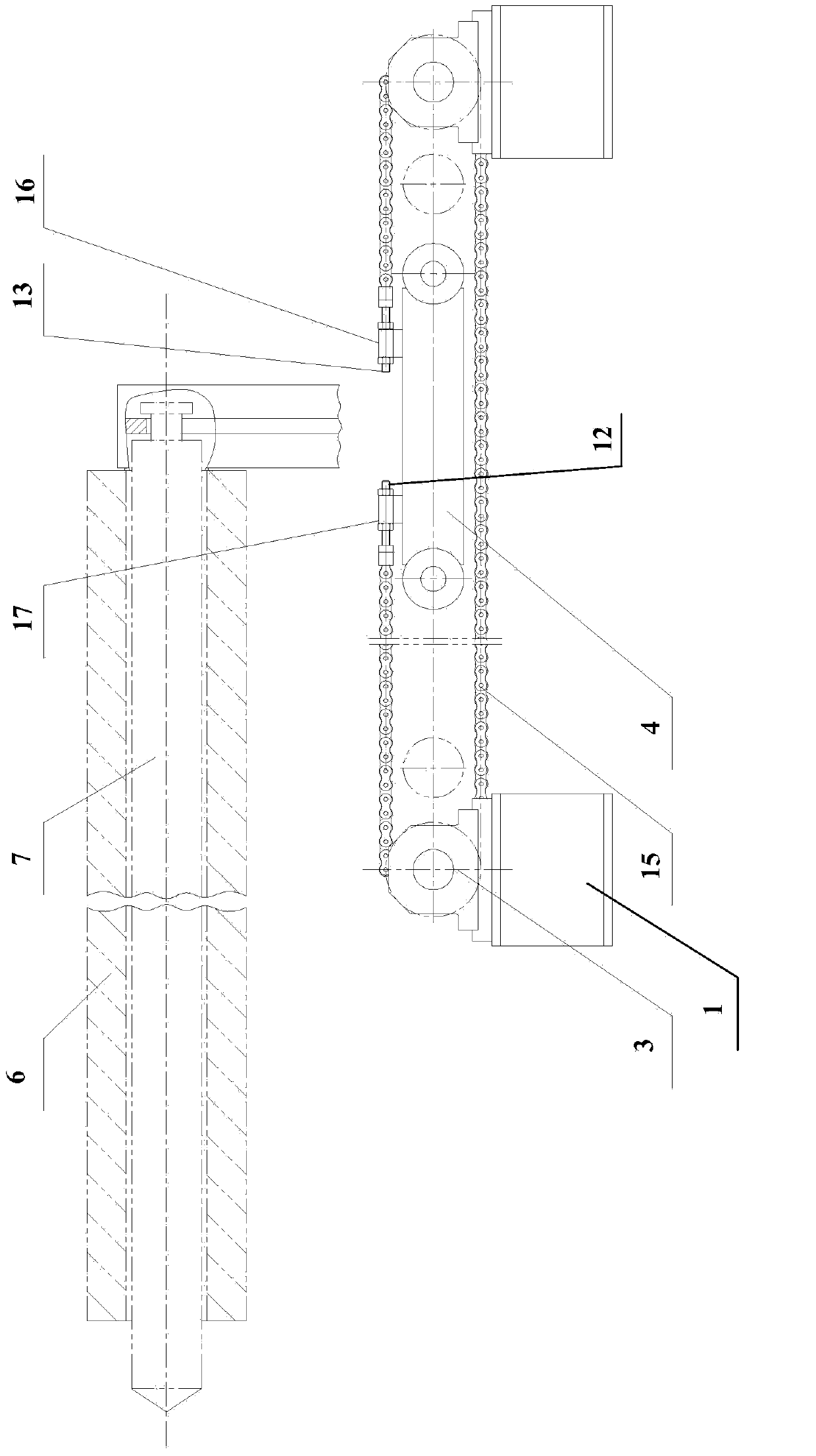
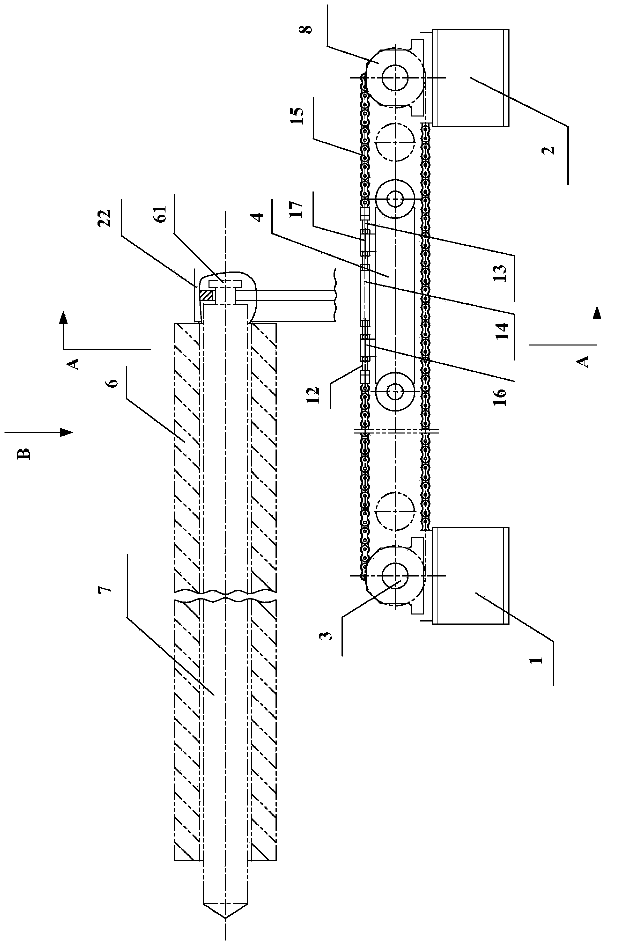
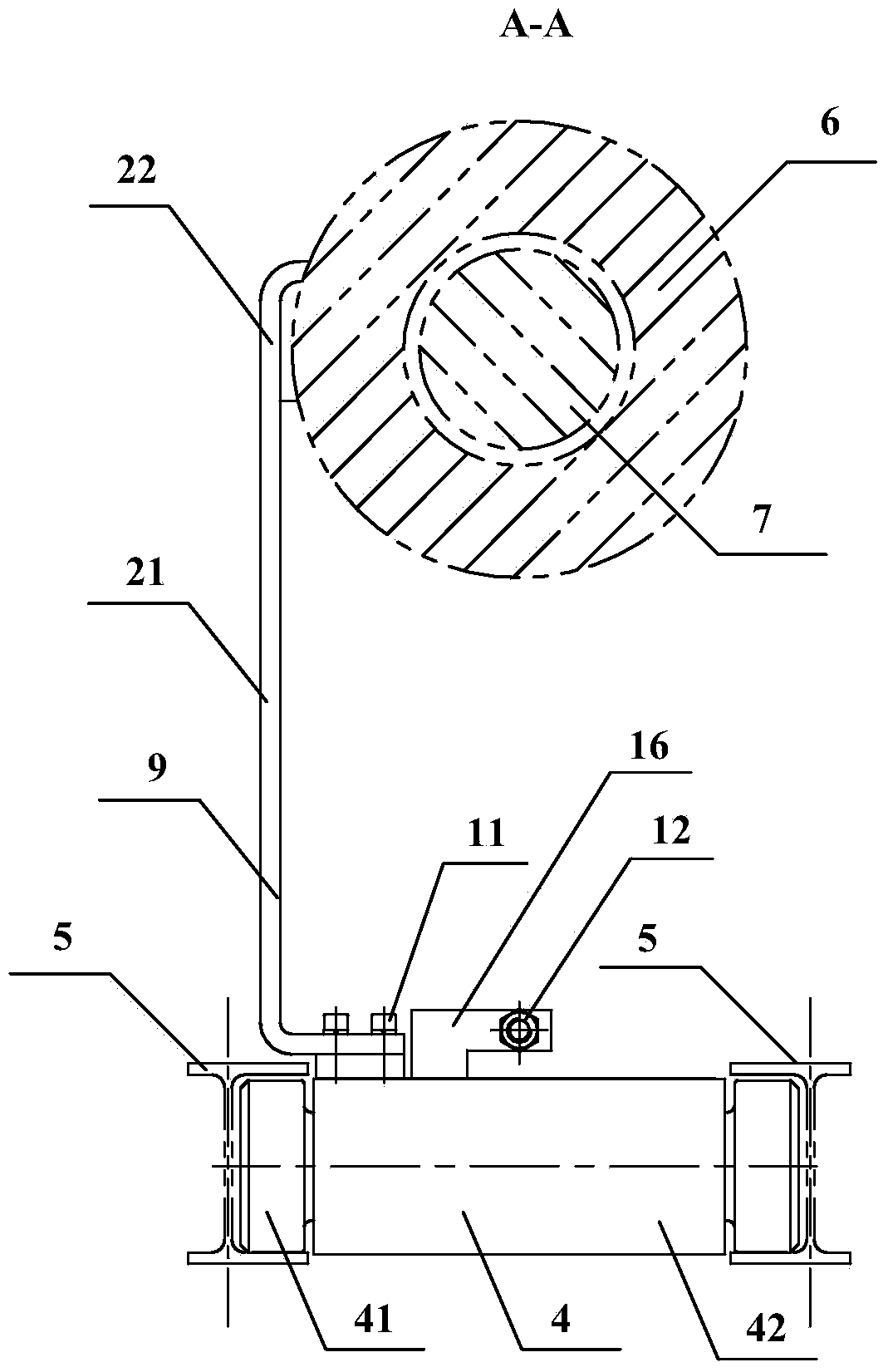
[0018] figure 2 Shown is the structural diagram of the cold-rolled pipe mill feeding mechanism of the present invention, image 3 shown as figure 2 The A-A line sectional schematic diagram, Figure 4 shown as figure 2 B direction view. refer to Figure 2-4 , The cold-rolled pipe mill feeding mechanism of the present invention comprises a chain 15, a push rod transport device 4, a track 5, a motor 1, a motor 2, a connecting rod 12, a connecting rod 13, a connecting device 14, a connecting block 17, a connecting block 16, Sprocket 3 and sprocket 8.

[0019] refer to Figure 2-4 , the push rod transport device 4 is arranged on the track 5 and moves along the track 5 . A connecting block 17 and a connecting block 16 are arranged on the push rod transportation device 4 , and both the connecting block 17 and the connecting block 16 are provided with through holes (not shown). The chain 15 is wound on the sprocket 3 and the sprocket 8 . The chain 15 is not closed but has ...


PUM


Abstract

The invention discloses a cold pilger mill feed-in mechanism. The feed-in mechanism comprises a chain arranged on two chain wheels in a wound mode, the chain is provided with an opening, a first connecting rod and a second connecting rod are arranged at the two ends of the opening of the chain respectively, and a first connecting block and a second connecting block are arranged on a push rod conveying device and respectively provided with a through hole. The first connecting rod penetrates through the first connecting block and then is fixed to one side of a connecting device, the second connecting rod penetrates through the second connecting block and then is fixed to the other side of the connecting device, moreover, the first connecting rod and the first connecting block are fixed, the second connecting rod and the second connecting block are fixed, and the first connecting rod, the second connecting rod, the chain and the connecting device form a closed loop structure together, and the chain is tensioned through the connecting device.

Description

technical field [0001] The invention relates to a cold rolling mill, in particular to a feeding mechanism of the cold rolling mill. Background technique [0002] figure 1 Shown is the structural diagram of the feeding mechanism of the existing cold rolling mill. Such as figure 1 As shown, two motors 1 drive two sprockets 3 to rotate, and the two sprockets 3 mesh with the chain 15. The length of the chain 15 can be tens of meters, and the push rod transport device 4 pushes the capillary 6 forward by pushing the mandrel 7; And the connecting block 17 is fixedly connected with the push rod transport device 4 by bolts; the connecting block 16 and the connecting block 17 all have through holes, and the connecting rod 12 and the connecting rod 13 installed at the head and tail of the chain 15 pass through the connecting block 16 and the connecting block respectively The through hole of 17 is fixedly connected with connection block 16 and connection block 17 by nut, and tension ...

Claims


Application Information

Patent Timeline
Patent Type & Authority Applications(China)
IPC IPC(8): B21B39/02
Inventor 张良夫秦臻王爱国方秋玲
Owner TAIYUAN HEAVY IND
Features
  • R&D
  • Intellectual Property
  • Life Sciences
  • Materials
  • Tech Scout
  • Unparalleled Data Quality
  • Higher Quality Content
  • 60% Fewer Hallucinations
Learn More