Pulling plug type magnetic lock capable of being locked through automatic spinning

A magnetic lock and pull bolt type technology, which is applied in building locks, locks controlled by non-mechanical transmission, buildings, etc., can solve the problem of failure of the pull bolt magnetic lock to lock, failure of the brake ring to move, and failure of the pull bolt to be pulled out, etc. problems, to achieve the effect of avoiding locking failure, saving effort in unlocking and locking, and simplifying the structure

Active Publication Date: 2014-02-19
SHANGHAI ONE TOP
View PDF7 Cites 7 Cited by
  • Summary
  • Abstract
  • Description
  • Claims
  • Application Information

AI Technical Summary

Problems solved by technology

[0004] It can be seen that the existing pull-bolt magnetic locks are all linearly moved between the brake ring (corresponding to the above-mentioned iron core 14) and the sleeve (corresponding to the above-mentioned ball-holding chamber 12) by the action of electromagnetic force, so that the pull bolt cannot be pulled out
In the case of small electromagnetic force, it is easy to cause the failure of the brake ring (iron core 14) to move relative to the sleeve (ball chamber 12), resulting in the failure of the pull-bolt magnetic lock

Method used


Image

  • Pulling plug type magnetic lock capable of being locked through automatic spinning
  • Pulling plug type magnetic lock capable of being locked through automatic spinning
  • Pulling plug type magnetic lock capable of being locked through automatic spinning

Examples


Embodiment Construction

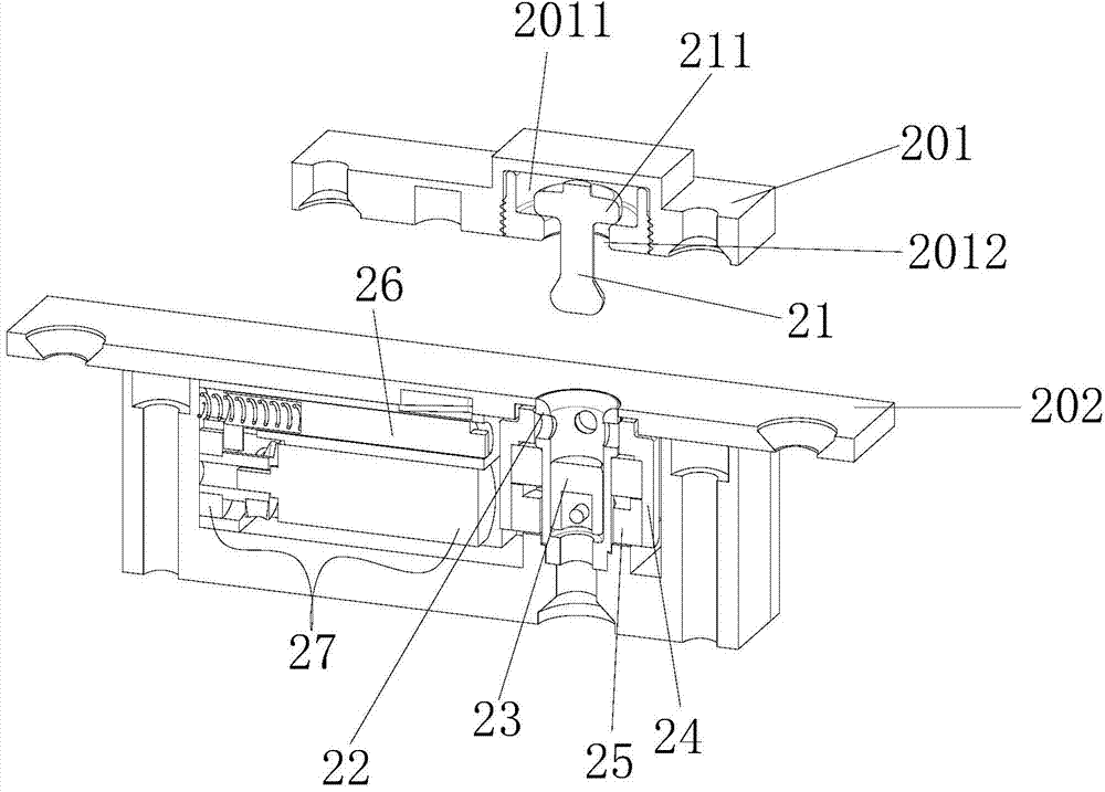
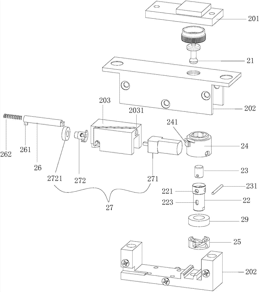
[0028] Such as figure 2 and image 3 As shown, the self-locking pull bolt magnetic lock according to an embodiment of the present invention includes a pull bolt 21 with a flange on the top of a vertical protrusion fixed on one side of the door, and an upper opening fixed on the other side of the door. The sleeve 22 that can be inserted into the pull bolt 21, the sleeve inner plug 23 that can move axially relative to the sleeve 22 in the sleeve 22, the brake ring 24 sleeved outside the sleeve 22, the brake ring 24 and the Between the sleeves 22, the rotating member 25, which can rotate synchronously with the brake ring 24, extends perpendicular to the axis of the brake ring 24, and one end cooperates with the radial deformation area 241 on the outer wall of the brake ring 24 to stop or release the brake. The bolt 26 of the moving ring 24 and the bolt driving assembly 27. The sleeve 22 and the brake ring 24 have a mechanism that cooperates with each other to adjust the apertu...


PUM


Abstract

The invention discloses a pulling plug type magnetic lock capable of being locked through automatic spinning. The lock comprises a pull bolt (21), a sleeve (22), a sleeve inner plug (23), a brake ring (24), a rotary piece (25), a plug pin (26) and a plug pin drive assembly (27), wherein the pulling bolt (21) is fixed to one side of the lock, the top end of the pulling bolt (21) is provided with a flange, the sleeve (22) is fixed to the other side of the lock and can be inserted to the pulling bolt, the sleeve inner plug (23) is arranged in the sleeve and can axially move relative to the sleeve, the sleeve (22) is sleeved with the brake ring (24), the rotary piece (25) is arranged between the brake ring and the sleeve and can synchronously rotate with the brake ring, the plug pin (26) extends perpendicular to the axial direction of the brake ring, and one end of the plug pin (26) is matched with the a radial deformed region (24) on the outer wall of the brake ring to lock or release the brake ring. The rotary piece can be driven by the sleeve inner plug to rotate under the action of the downward force of the pulling bolt, and can be driven by the brake ring to rotate back under the action of the upward force of the pulling bolt. The pulling plug type magnetic lock capable of being locked through automatic spinning prevents ineffective locking caused by small electromagnetic force, and can achieve locking and unlocking with very small electromagnetic force; unlocking is achieved with the assist of the mechanical force, the lock structure is simplified, and working is more reliable.

Description

technical field [0001] The invention relates to a pull bolt type magnetic force lock, in particular to a pull bolt type magnetic force lock which spins and locks. Background technique [0002] An existing pull bolt type magnetic lock such as figure 1 As shown, on one side, a pull bolt 11 is set on the base plate 103 of the door, iron plates 104 are set on both sides of the pull bolt 11, on the other side, a cylindrical ball-holding cavity 12 is set on the door frame, and in the ball-holding cavity 12 A circular hole 121 is opened in the wall of the circular hole 121, and balls are placed in the circular hole 121. An axially sliding iron core 14 is set on the outer ring of the ball chamber 12, and there are two stepped holes with different diameters in the iron core 14. Wherein, the pull bolt 11 is a cylindrical rod with a ball at one end protruding perpendicular to the door panel, and the diameter of the ball at the end of the pull bolt 11 is larger than the diameter of the...

Claims


Application Information

Patent Timeline
IPC IPC(8): E05B47/06
Inventor 张宗志
Owner SHANGHAI ONE TOP
Why Eureka
Try Eureka