Internal circulation type locomotive LED lamp head structure

A technology of LED lamp head and internal circulation, which is applied in the direction of motor vehicles, road vehicles, lighting devices, etc.

Inactive Publication Date: 2014-02-19
郝明刚
View PDF4 Cites 1 Cited by
  • Summary
  • Abstract
  • Description
  • Claims
  • Application Information

AI Technical Summary

Problems solved by technology

[0005] There is no information at home and abroad to show that

Method used


Image

  • Internal circulation type locomotive LED lamp head structure
  • Internal circulation type locomotive LED lamp head structure
  • Internal circulation type locomotive LED lamp head structure

Examples


Embodiment Construction

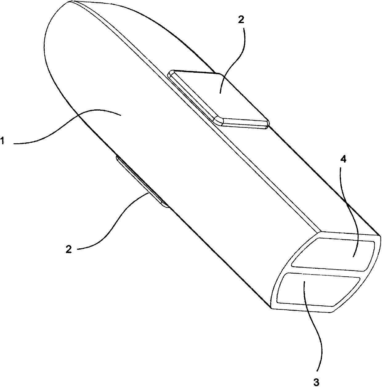
[0011] The schematic diagram of the appearance of the structure of the LED lamp head of the inner circulation type locomotive of the present invention is as follows: figure 1 As shown: It is composed of LED lamp holder 1, LED light source 2, inlet channel 3, outlet channel 4 and other main components.

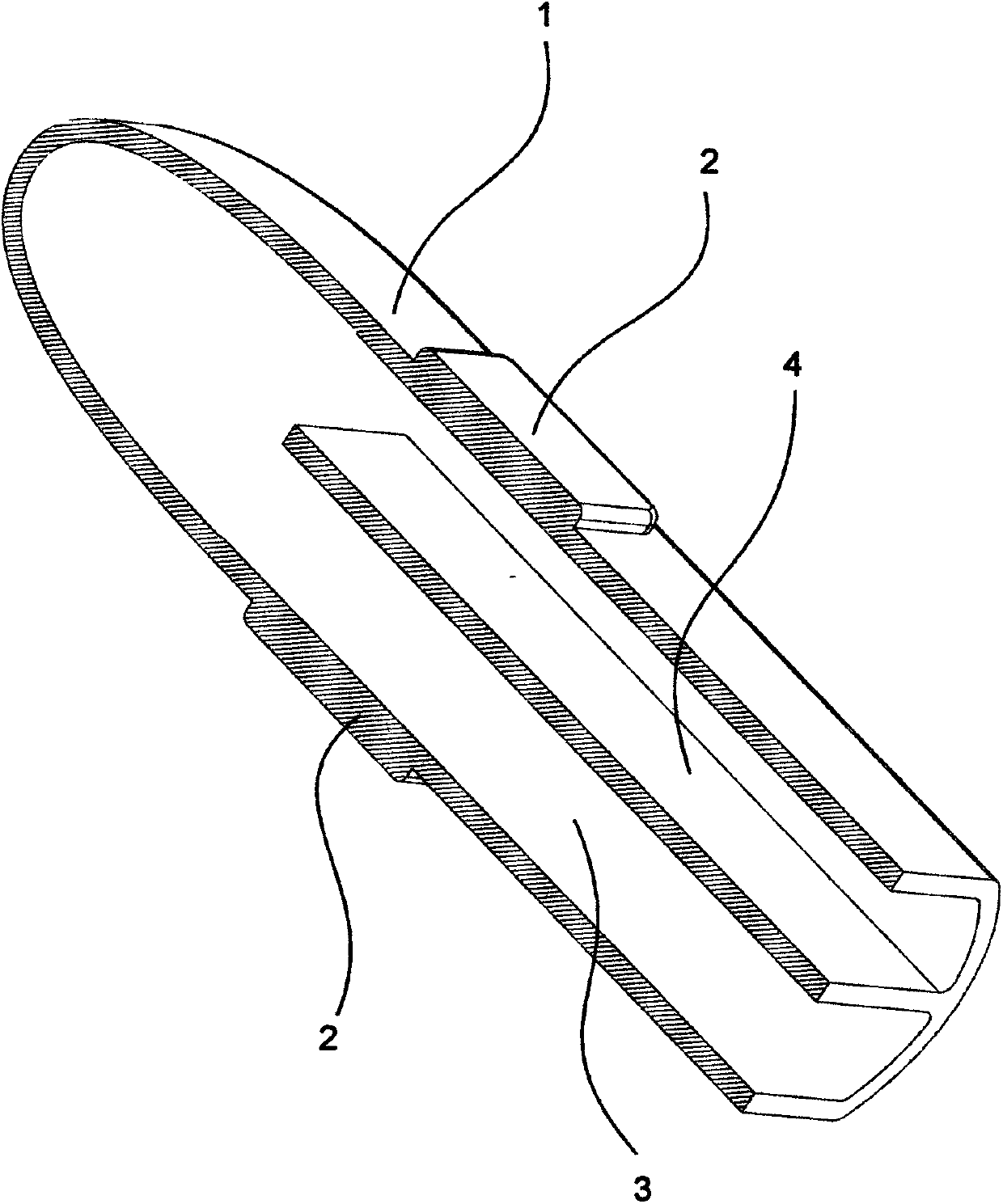
[0012] The mechanical relationship is as follows: the LED light source 2 is fixedly connected to the outside of the LED lamp cap 1, and the interior of the LED lamp cap 1 is isolated into the inlet channel 3 and the outlet channel 4, and the ends of the inlet channel 3 and the outlet channel 4 are connected. Schematic such as figure 2 shown.

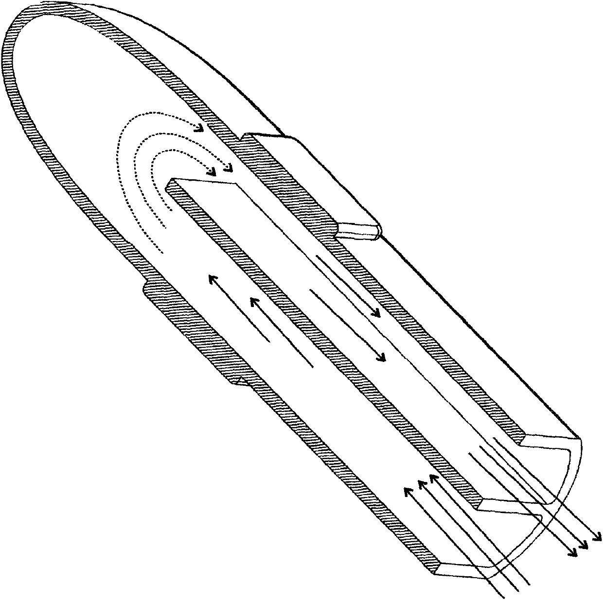
[0013] working principle:

[0014] When the motorcycle LED light of the present invention is working, the LED light source 2 emits light and generates a large amount of heat. The end of the flow channel 3 flows back into the outlet channel 4, and flows through the entire LED lamp head 1 again, and then flows out of the LED lamp head 1...


PUM


Abstract

The invention provides an internal circulation type locomotive LED lamp head structure which is characterized in that at leas one LED light-emitting source is fixedly connected to the outer side of a locomotive LED lamp head, the inside of the locomotive LED lamp head is divided into at least one inlet channel and at least one outlet channel, and the tail end of the inlet channel and the tail end of the outlet channel are communicated. In work, heat generated when the LED light-emitting source outside the locomotive LED lamp head works is conducted to air or liquid flowing in the internal circulation channels of the lamp head, and heat is dissipated out of the LED lamp head by the flowing air or liquid in a forced mode.

Description

technical field [0001] The invention relates to a structure of an LED lamp for a motorcycle, in particular, the heat dissipation method of the LED lamp for a motorcycle mainly relies on cooling gas or liquid circulating in an inlet channel and an outlet channel of the LED lamp head to take away heat. Background technique [0002] With the continuous development of LED lighting technology, its luminous efficiency far exceeds any other electronic equipment, and its application in locomotive lighting has been in the ascendant in recent years. When installing LED lights, the first thing to consider is the heat dissipation of the LED lights. [0003] The LED light source on the traditional high-power locomotive LED lights on the market will generate a lot of heat while emitting light. Because the lamp head is limited by the installation space, it cannot be thick enough to conduct heat, so the traditional high-power motorcycle LED lights have the problem of poor heat dissipation....

Claims


Application Information

Patent Timeline
IPC IPC(8): F21S8/10F21V29/00F21W101/02F21Y101/02F21V29/56F21V29/60F21W107/10F21Y115/10
Inventor 郝明刚
Owner 郝明刚
Why Eureka
Try Eureka