oil separator

A technology of oil separator and oil shield, which is applied in the direction of refrigeration components, refrigerators, lighting and heating equipment, etc. It can solve the problems of low oil separation efficiency and unsuitability for large and medium-sized air conditioning systems, and achieve high oil separation efficiency and capacity big effect

Inactive Publication Date: 2016-03-09
GREE ELECTRIC APPLIANCES INC
View PDF6 Cites 0 Cited by
  • Summary
  • Abstract
  • Description
  • Claims
  • Application Information

AI Technical Summary

Problems solved by technology

[0004] Based on this, it is necessary to provide a solution for the problem that the straight-through oil separator has high oil separation efficiency but is not suitable for large and medium-sized air conditioning systems, while the vertical oil separator is suitable for large and medium-sized air conditioning systems but has low oil separation efficiency. oil separator

Method used


Image

  • oil separator
  • oil separator
  • oil separator

Examples


Embodiment Construction

[0022] The present invention will be further described below in conjunction with the accompanying drawings and specific embodiments.

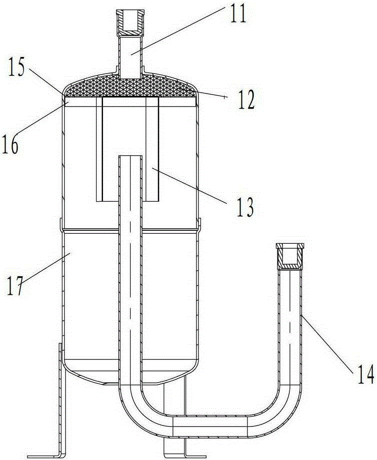
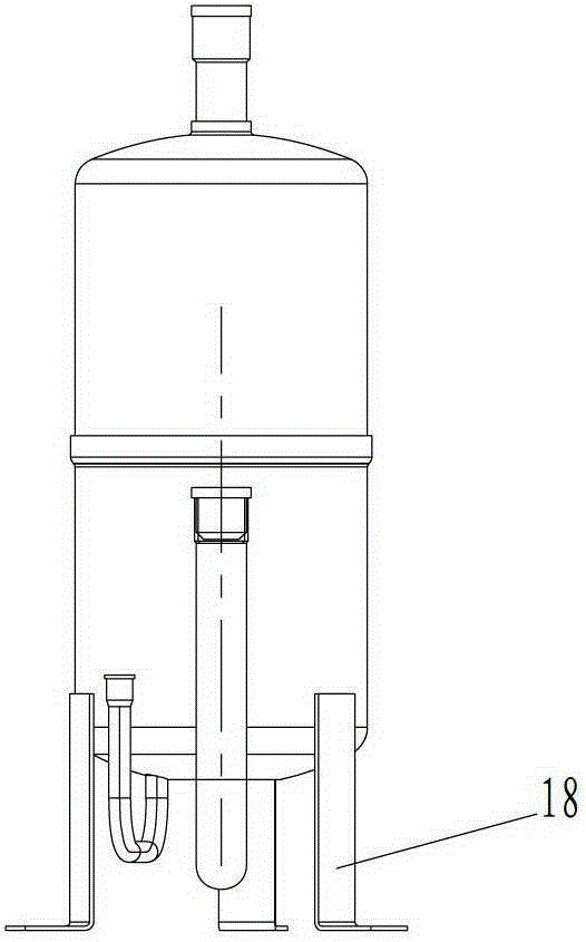
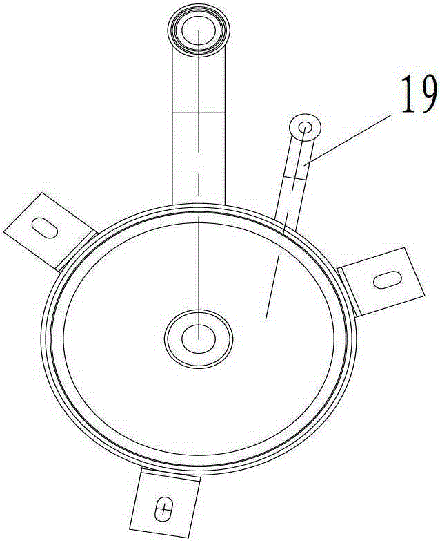
[0023] Such as Figure 1-A , Figure 1-B and Figure 1-C As shown, the present invention includes a cylinder body 17, an air inlet pipe 11, an air outlet pipe 14, an oil return pipe 19 and a foot 18; the top of the cylinder body 16 has a first through hole, and the bottom of the cylinder body 17 has a second through hole , the air inlet pipe 11 and the air outlet pipe 14 extend vertically into the inside of the cylinder 17 through the first through hole and the second through hole respectively; the bottom of the cylinder 17 also has a third through hole hole, the oil return pipe 19 passes through the third through hole into the bottom of the barrel 17, and the third through hole is adjacent to the second through hole;

[0024] The oil separator also includes a filtering device and an oil retaining device, and the filtering device and the oil ...


PUM


Abstract

The invention provides an oil separator. The oil separator comprises a cylinder body, an air inlet pipe, an air outlet pipe and an oil return pipe. The top of the cylinder body is provided with a first through hole, and the bottom of the cylinder body is provided with a second through hole; the air inlet pipe and the air outlet pipe extend inside the cylinder body through the first through hole and the second through hole respectively; the bottom of the cylinder body is provided with a third through hole, and the oil return pipe extends inside the cylinder body through the third through hole. The oil separator also comprises a filtering device and an oil retaining device which are sequentially arranged inside the cylinder body from top to bottom, the filtering device is arranged at the air outlet end of the air inlet pipe, and the air outlet pipe extends inside the oil retaining device. According to the above structure of the oil separator, the filtering device and the oil retaining device achieve double oil separation, so that the oil separation efficiency is higher and meanwhile the oil storage function can be obtained. By means of a vertical type structure, the oil separator has relatively large capacities, thereby being applicable to large air conditioning systems.

Description

technical field [0001] The invention relates to a separation device, in particular to an oil separator. Background technique [0002] The oil separator is a commonly used gas-liquid separation device; it is one of the necessary components in large and medium-sized air-conditioning systems. It is installed at the exhaust port of the air-conditioning compressor to separate the lubricating oil in the high-temperature gas discharged from the compressor. Through the oil return loop, it returns to the compressor through the suction end of the compressor, so as to ensure the lubrication requirements of the compressor and the operation of the system. [0003] The structure of oil separator generally includes three types: horizontal type, vertical type and straight-through type. Among them, the straight-through oil separator is generally equipped with a filter screen to filter and separate the lubricating oil in the oil-gas mixture, and the oil separation efficiency is high. However...

Claims


Application Information

Patent Timeline
Patent Type & Authority Patents(China)
IPC IPC(8): F25B43/02
Inventor 沈军王永立邹云霞胡强陈振松王瑞强王少山
Owner GREE ELECTRIC APPLIANCES INC
Why Eureka
Try Eureka