Exhaust pipe structure and compressor

A technology for exhaust pipes and compressors, applied in the field of compressors, which can solve the problems of reduced compressor performance, low oil separation efficiency, and short flow channels, etc., to achieve the effects of extending flow channels, improving oil separation efficiency, and increasing the collision separation process

Active Publication Date: 2020-12-25
GREE ELECTRIC APPLIANCES INC
View PDF10 Cites 0 Cited by
  • Summary
  • Abstract
  • Description
  • Claims
  • Application Information

AI Technical Summary

Problems solved by technology

[0002] At present, the structure of the screw compressor is relatively small, the internal space is compact, the distribution of the flow field at the exhaust end is uneven, and the flow path in some places is too short, resulting in the end of the oil and gas separation before it is completely separated, and the oil separation efficiency is relatively low.
Because the oil separation efficiency is not high, the system needs to increase its oil return to ensure the stable operation of the compressor. The increase in the oil return will greatly affect the volumetric efficiency of the compressor, resulting in a decrease in the performance of the compressor

Method used


Image

  • Exhaust pipe structure and compressor

Examples


Embodiment Construction

[0020] The present invention will be described in detail below with reference to the accompanying drawings and examples.

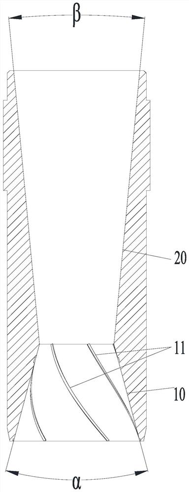
[0021] like figure 1 As shown, according to the structure of the exhaust pipe of the present invention, along the direction of airflow, there is a converging section 10 and a diverging section 20 inside the exhaust pipe. In the present invention, by setting the tapering section 10 and the diverging section 20, the oil-gas mixture will collide with the inner wall surface of the exhaust pipe tapering section 10 during the exhaust process, so that the oil and gas are separated. Then through the gradual expansion section 20, the airflow expands gradually, and finally discharges out the exhaust pipe relatively uniformly. Compared with the existing exhaust process, the entire process has a significantly longer flow path, and increases the collision separation process, effectively improving the oil separation efficiency.

[0022] Specifically, the end of the co...


PUM


Abstract

The invention provides an exhaust pipe structure and a compressor. According to the exhaust pipe structure, a gradual contraction section and a gradual enlargement section are arranged in an exhaust pipe in the air flow direction; through the arrangement of the gradual contraction section and the gradual enlargement section, an oil-gas mixture hits against the inner wall surface of the gradual contraction section of the exhaust pipe during the exhaust process, so that oil-gas separation can be realized; besides, the air flow gradually expands when passing through the gradual enlargement section to be uniformly exhausted from the exhaust pipe at last; compared with the conventional exhaust process, the exhaust pipe structure has the advantages that during the overall exhaust process the flow channel is obviously lengthened, the collision separation process is added, and the oil separation efficiency is effectively improved.

Description

technical field [0001] The invention relates to the field of compressors, in particular to an exhaust pipe structure and a compressor. Background technique [0002] At present, the structure of the screw compressor is relatively small, the internal space is compact, the flow field distribution at the exhaust end is uneven, and the flow path in some places is too short, resulting in the oil and gas being separated before they are completely separated, and the oil separation efficiency is relatively low. Because the oil separation efficiency is not high, the system needs to increase its oil return volume to ensure the stable operation of the compressor. The increase in the oil return volume will greatly affect the volumetric efficiency of the compressor, resulting in a decrease in the performance of the compressor. SUMMARY OF THE INVENTION [0003] The present invention aims to provide an exhaust pipe structure and a compressor capable of improving oil separation efficiency....

Claims


Application Information

Patent Timeline
Patent Type & Authority Patents(China)
IPC IPC(8): F04C29/12
CPCF04C29/12
Inventor 晏杰张贺龙肖有为张宝鸽曹聪孟强军袁皓李日华
Owner GREE ELECTRIC APPLIANCES INC
Why Eureka
Try Eureka