Oil-water mixture oil separation tank and oil separation system for swill separation

An oil-water mixture and oil tank technology, which is applied in separation methods, liquid separation, auxiliary equipment for liquid separation, etc., can solve the problems of insufficient purity and high water content in oil.

Active Publication Date: 2021-10-26
ANHUI TIANJIAN ENVIRONMENTAL PROTECTION
View PDF0 Cites 0 Cited by
  • Summary
  • Abstract
  • Description
  • Claims
  • Application Information

AI Technical Summary

Problems solved by technology

[0004] In order to solve the technical problem that the oil separated from the existing oil-water separation tank for kitchen swill contains more water and is not pure enough, the present invention provides an oil-water mixture oil separation tank for swill separation and its oil separation system

Method used


Image

  • Oil-water mixture oil separation tank and oil separation system for swill separation
  • Oil-water mixture oil separation tank and oil separation system for swill separation
  • Oil-water mixture oil separation tank and oil separation system for swill separation

Examples


Embodiment 1

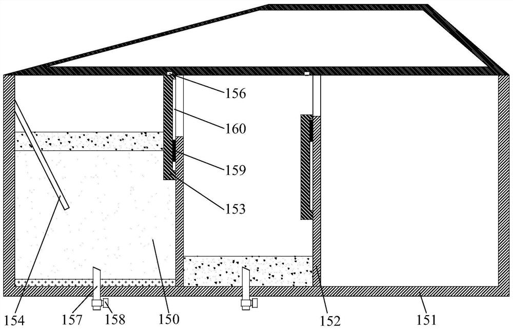
[0064] see figure 1 ,本实施例提供了一种泔水分离用的油水混合物隔油箱,其用于对油水混合液进行隔油分离,使液体按照密度分离成油层和水层。其中,该油水混合物隔油箱包括箱体151、隔板152、悬浮板153、缓冲板154、排水管157、水阀158以及进出料控制器,还可以包括进料管以及进料阀。

[0065] 箱体151可以由多块组装板组成,也可以采用一体成型结构进行使用。 箱体151的内外表面可以涂覆耐油涂料,可以保证油污不会腐蚀或堆积在箱体151的内壁或者外壁上。 箱体151上可以开设进料口,外部输入的油水混合物 / 液从进料口进入到箱体151内并在重力的作用下分层,上层为油层,而下层为水层,最下层为沉淀 Floor.

[0066] 隔板152的数量为多块,并且多块隔板152设置在箱体151中,而且平行设置,以将箱体151的内腔从其一侧至其另一侧分隔成相互连通的多个隔油空间163。其中,相邻的两个隔油空间163通过一块隔板152的上部空间连通。从箱体151的内腔的一侧至其另一侧,隔板152的高度依次增加,这样位于上层的油层会逐步转移至后一个隔油空间163,这样位于箱体151的内腔的另一侧的隔油空间163中的油层的厚度会非常大,从而收集到更多的油脂。这样,在油水混合物进入到前端的隔油空间163后,位于上层的油层会从该上部空间流入到另一个隔油空间163,如此往复,实现对油水混合物中油层和水层的多次分隔,使得最终分离出的油液中的含水率大大降低。隔板152靠近对应的悬浮板153的一侧具有凸条159,凸条159的数量至少为一根,并且凸条159的表面光滑。

[0067] 悬浮板153的数量为多块,而且每块悬浮板153与一块隔板152对应。每块悬浮板153活动安装在对应的隔板152上,并能够通过移动而盖住对应的隔板152的上部空间,以使位于对应的隔板152两侧的两个隔油空间163隔绝。其中,悬浮板153的密度位于油水混合物的油密度和水密度之间。在本实施例中,悬浮板153靠近对应的隔板152的一侧开设凹槽160,凹槽160的数量至少为一个,而且每个凹槽160与一根凸条159对应,并且每根凸条159限位在对应的凹槽160中。定义每块悬浮板153在纯净水中的浮力为F 1 ,每块悬浮板153在对应的隔板152上受到的摩擦力为F 2 ,每块悬浮板1...

Embodiment 2

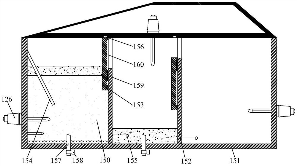
[0078] see figure 2 , the present embodiment provides an oil-water mixture oil separation tank for swill separation, and the oil separation tank adds a heating pipe 126, a temperature sensor 155 and a temperature controller on the basis of Embodiment 1.

[0079] There are multiple heating pipes 126 , and the multiple heating pipes 126 correspond to the multiple oil separation spaces 163 respectively. The heating pipe 126 is installed on the box body 151 and protrudes into the corresponding oil-separating space 163 for heating the oil-water mixture in the corresponding oil-separating space 163 . The heating tube 126 can be an existing heating tube, such as a U-shaped heating tube, which can keep the oil-water mixture in a liquid state all the time, so that the oil-water can be stratified without condensation.

[0080] There are multiple temperature sensors 155 , and each temperature sensor 155 corresponds to one heating pipe 126 . The temperature sensor 155 is installed on t...

Embodiment 3

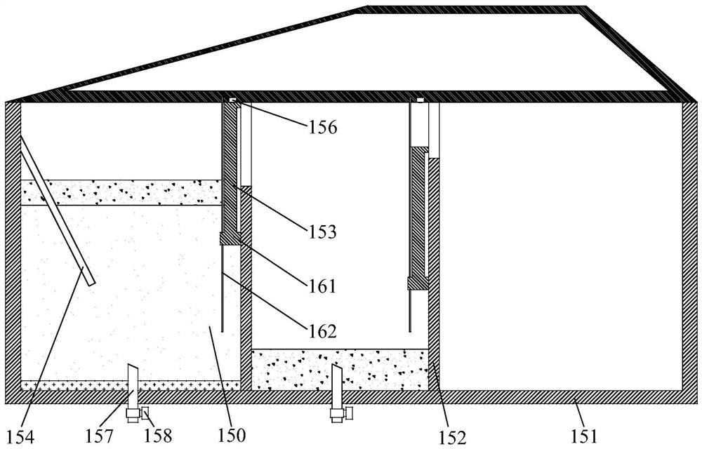
[0084] see image 3 , this embodiment provides an oil-water mixture oil-separation tank for swill separation, which is similar to that of Embodiment 1, except that the structure of the suspension plate 153 and the separator 152 is different. The bottom end of the suspension board 153 has steps 161, and the number of steps 161 is at least one layer. A sliding rod 162 is provided on a side of the partition 152 close to the corresponding suspension plate 153 , the number of the sliding rod 162 is at least one, and each sliding rod 162 corresponds to a step 161 . Each sliding rod 162 passes through the corresponding step 161 and is fixed on the top wall of the box body 151 . Moreover, lubricating oil can be provided at the connecting part of the sliding rod 162 and the sliding rod 162, and a smooth structure can also be used to reduce the friction between the sliding rod 162 and the step 161 and reduce the resistance of the suspension board 153, so that the suspension board 153 c...


PUM


Abstract

The invention discloses an oil-water mixture oil separation tank for swill separation and an oil separation system thereof. The oil-water mixture oil trap for swill separation includes a box body, a partition, a suspension plate, a buffer plate, a touch switch, a drain pipe, a water valve, and a material inlet and outlet controller. The partition divides the box into multiple oil-separating spaces, and two adjacent oil-separating spaces communicate through the upper space of the partition. The suspension board moves to cover the upper space of the corresponding partition, and the density of the suspension board is between the oil density and the water density. The touch switch is located above the corresponding suspension board, and the suspension board can press against the corresponding touch switch, so that the touch switch generates a switch signal. One end of each drainage pipe is arranged in the oil separation space, and the other end is located outside the box. The water valve is used to open or close the corresponding drain pipe. When the input and output controller generates a switch signal by touching the pressure switch, it drives the corresponding water valve to open the corresponding drain pipe. The invention can reduce the water content and improve the purity of oil-water separation.

Description

technical field [0001] The invention relates to an oil separation tank in the technical field of kitchen waste treatment, in particular to an oil-water mixture oil separation tank for swill separation. Background technique [0002] Swill is a kind of domestic waste formed by residents in the process of daily consumption. The various organic substances contained in it are very easy to corrode in summer; the leftover soup and rancid water contain a lot of it, which is easy to cause waste in the process of garbage collection and transportation. Pollution; at the same time, kitchen swill is the main source of leachate in landfills, and it is also an important cause of air pollution and fly breeding; the swill pigs fed by swill and the swill oil extracted to the market seriously endanger human health. A large amount of kitchen swill has become the main source of urban pollution and harm to human health. [0003] At present, there are generally two ways to collect kitchen swill a...

Claims


Application Information

Patent Timeline
Patent Type & Authority Patents(China)
IPC IPC(8): B01D17/032B01D17/12C02F1/40
CPCB01D17/0214B01D17/12C02F1/40
Inventor 孟行健
Owner ANHUI TIANJIAN ENVIRONMENTAL PROTECTION
Why Eureka
Try Eureka