Solar thermal storage system

A heat storage system and solar energy technology, applied in the field of solar heat storage systems, can solve problems such as temperature imbalance of heat storage units and low heat storage efficiency of heat storage systems, and achieve low production costs, high heat storage efficiency, and increased heat exchange area Effect

Inactive Publication Date: 2014-02-19
深圳市联讯创新工场科技开发有限公司
View PDF6 Cites 9 Cited by
  • Summary
  • Abstract
  • Description
  • Claims
  • Application Information

AI Technical Summary

Problems solved by technology

[0004] The technical problem to be solved by the present invention is that the temperature imbalance between the heat storage units of the existing solar heat storage system leads to the problem of low heat storage efficiency of the heat storage system, and further provides a method that can balance the temperature of the heat storage modules inside the heat storage system and has high heat storage efficiency solar heat storage system

Method used


Image

  • Solar thermal storage system
  • Solar thermal storage system
  • Solar thermal storage system

Examples


Embodiment 1

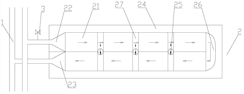
[0049] figure 1 The solar heat storage system of the present invention includes a heat storage pile 2; the heat storage pile 2 is connected to the main pipeline 1 through an inlet 22 and an outlet 23; the heat storage pile 2 includes a thermally insulated heat storage chamber 24 and The heat storage unit 21 arranged inside the heat storage chamber 24. In this embodiment, two rows of the heat storage units 21 are arranged in the heat storage chamber 24 corresponding to the positions of the inlet 22 and the outlet 23, far away from the heat storage chamber 24. A main channel gap 26 is provided between the end of the heat storage unit 21 of the inlet 22 and the outlet 23 and the inner wall of the rear end of the heat storage chamber 24; a gap 26 is provided between adjacent heat storage units 21 in each row There is an auxiliary channel gap 27; the thermal working medium flows into a row of heat storage units 21 connected to the inlet 22 through the inlet 22, and after passing th...

Embodiment 2

[0054] The structure of this embodiment is basically the same as that of Embodiment 1, the difference is that the heat storage unit 21 is composed of a plurality of heat storage pipes 215 arranged in a staggered manner and interconnected with each other, and scattered storage pipes 215 arranged between the heat storage pipes 215. Heat medium composition. Between the main passage gap 26 and the auxiliary passage gap 27, a number of stacked ventilation bricks 29 are arranged, and the ventilation bricks 29 are blocks with through holes in four directions.

Embodiment 3

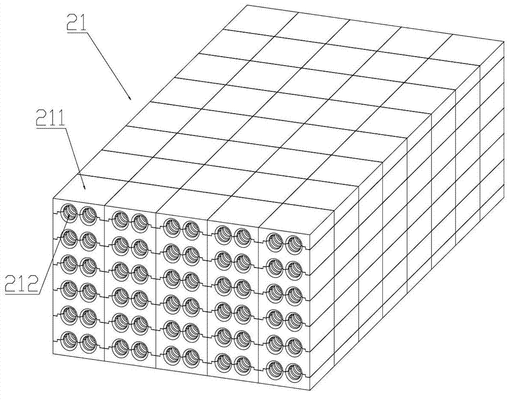
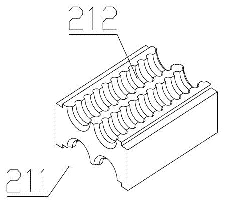
[0056] The structure of this embodiment is basically the same as that of Example 1, the difference is that: the heat storage unit 21 includes a row of heat storage modules 211 and loose heat storage media arranged on both sides of the heat storage modules 211, the heat storage The heat storage medium is sandstone. The surface or inside of the heat storage module 211 is formed with the thermal medium channels 212 communicating with each other horizontally and vertically. Between the main passage gap 26 and the auxiliary passage gap 27, a number of stacked ventilation bricks 29 are arranged, and the ventilation bricks 29 are blocks with through holes in four directions.


PUM


Abstract

The invention discloses a solar thermal storage system comprising at least one thermal storage pile. The thermal storage pile is communicated with a main pipeline through an inlet and an outlet, and comprises an adiabatic thermal storage chamber and at least two thermal storage units arranged inside the thermal storage chamber. One thermal storage unit is communicated with the inlet, and the other thermal storage unit is communicated with the outlet. Hot working medium channels are arranged inside the thermal storage units. Hot working medium flows into the hot working medium channels of the thermal storage units from the main pipeline through the inlet, flows through the entire storage pile and then flows back to the main pipeline through the outlet; main thermal transmitting channels of the hot working medium are formed. Auxiliary thermal transmitting channels used for balancing thermal among the thermal storage units are further arranged inside the thermal storage chamber, the thermal storage units with higher temperature transmit the thermal of the hot working medium to the thermal storage units with lower temperature through the auxiliary thermal transmitting channels. The problems that according to an existing solar thermal storage system, since temperatures of thermal storage modules are imbalanced, thermal storage efficiency of the thermal storage system is low are solved.

Description

technical field [0001] The invention belongs to the field of solar heat storage systems, in particular to a heat storage system for solar power generation. Background technique [0002] Of all the renewable energy sources, solar energy is the most widely distributed and the easiest to obtain. However, solar energy is affected by regular changes such as geography, day and night, and seasons, as well as random factors such as cloudy, cloudy and rainy, so the energy presents instability and discontinuity. In order to ensure the stable operation of solar energy utilization, heat storage devices are required to store solar energy and release it when solar energy is insufficient to meet the needs of continuous and stable supply of energy for production and living. At present, research on solar energy storage methods at home and abroad mainly focuses on the selection of heat storage materials and heat storage methods. As for the selection of heat storage materials, solid material...

Claims


Application Information

Patent Timeline
Patent Type & Authority Applications(China)
IPC IPC(8): F28D20/00
CPCY02E10/44Y02E70/30F24J2/04F28D20/00Y02E60/142F24S60/00F28D20/0056F28F7/02Y02E10/40Y02E60/14
Inventor 孙海翔朱亮许迪窦新国钟强
Owner 深圳市联讯创新工场科技开发有限公司
Why Eureka
Try Eureka