Hydraulic system for construction machinery

A technology for construction machinery and hydraulic systems, applied in the field of hydraulic systems, can solve the problems of deviation of construction machinery from the line, pressure loss, and hydraulic fluid cannot be supplied equally.

Inactive Publication Date: 2014-02-19
VOLVO CONSTR EQUIP AB
View PDF9 Cites 13 Cited by
  • Summary
  • Abstract
  • Description
  • Claims
  • Application Information

AI Technical Summary

Problems solved by technology

[0009] On the other hand, when performing a combined operation of a traveling device and a working device such as a boom, the hydraulic fluid from the first load sensing line 17 flows through the first throttle valve 18 connected to the hydraulic oil tank, and from the second load The hydraulic fluid of the sensing line 19 flows through the second throttle valve 20 connected to the hydraulic oil tank, causing a pressure loss and thus a load acting on the first pressure compensating valve 12 and the third pressure compensating valve 14 of the traveling device There is a difference between the sensed pressure
[0010] Therefore, when a combined operation of a traveling device and a working device such as a boom is performed, hydraulic fluid cannot be equally supplied to the left traveling motor 6 and the right traveling motor 8, and this may cause generation of off-line traveling of the construction machine.

Method used


Image

  • Hydraulic system for construction machinery
  • Hydraulic system for construction machinery
  • Hydraulic system for construction machinery

Examples


Embodiment Construction

[0055] Hereinafter, preferred embodiments of the present invention will be described in detail with reference to the accompanying drawings. Matters such as detailed construction and elements defined in the description are merely specific details provided to help those of ordinary skill in the art fully understand the present invention, and the present invention is not limited to the embodiments disclosed hereinafter.

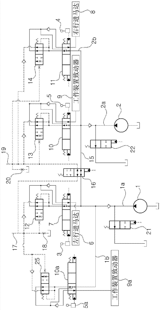
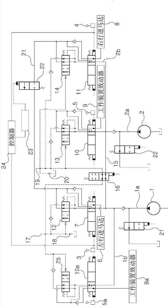
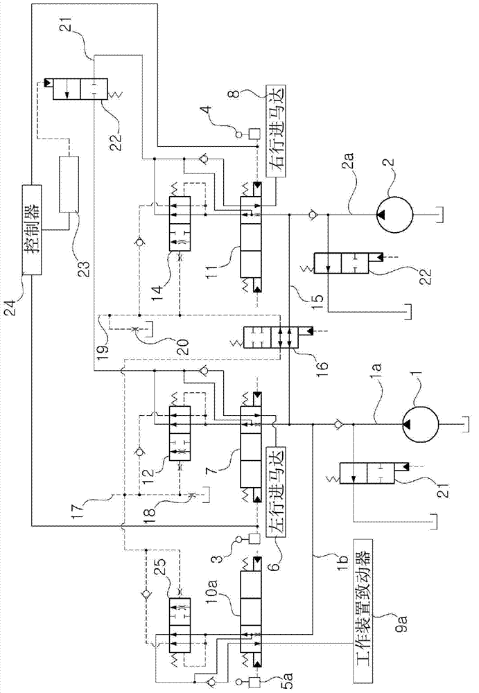
[0056] Such as figure 2 As shown in , the hydraulic system for construction machinery according to the first embodiment of the present invention includes: a first hydraulic pump 1 and a second hydraulic pump 2, connected to an engine (not shown); a left travel operating lever 3, a right The traveling operation lever 4 and the actuator operating lever 5a for the first working device and the actuator operating rod 5 for the second working device output an operation signal proportional to the operator's operation amount; the left traveling motor 6 , is connected ...


PUM


Abstract

Disclosed is a hydraulic system for construction machinery adapted to prevent the occurrence of off-course travel when performing a composite action on a working device such as a boom and vehicle travel. In the hydraulic system for construction machinery according to the present invention, provided is a system which comprises: a first and a second hydraulic pump; operating levers for a left and a right side travel operating device and a first and second working device; an actuator for a left-side travel motor and the first working device, the actuator being connected to the discharge flow pathway of the first hydraulic pump; an actuator for a right-side travel motor and the second working device, the actuator being connected to the discharge flow pathway of the second hydraulic pump; a first pressure compensating valve which is provided on one side, being either the upstream side or the downstream side, of a first control valve; a second pressure compensating valve which is provided on one side, being either the upstream side or the downstream side, of a second control valve; a third pressure compensating valve which is provided on one side, being either the upstream side or the downstream side, of a third control valve; a fourth pressure compensating valve which is provided on one side, being either the upstream side or the downstream side, of a fourth control valve; a first orifice which connects, to a hydraulic pressure tank, a first load sensing line connected to the first pressure compensating valve of the first control valve and the fourth pressure compensating valve of the fourth control valve; a second orifice which connects, to a hydraulic pressure tank, a second load sensing line connected to the second pressure compensating valve of the second control valve and the third pressure compensating valve of the third control valve; a flow combining valve which is provided in a flow combining flow pathway of the first and second hydraulic pumps; a travel link-through valve which is provided in a flow pathway connecting the downstream of the first pressure compensating valve and the downstream of the third pressure compensating valve; and a control unit for implementing control in such a way as to effect through linkage of the travel link-through valve during composite action involving operation of the working device and vehicle travel.

Description

technical field [0001] The invention relates to a hydraulic system for engineering machinery. More specifically, the present invention relates to a hydraulic system for a construction machine capable of preventing the construction machine from It is possible to improve operability by traveling off-course. Background technique [0002] In general, in the case of operating a working device (eg boom or arm) in a hydraulic system with two or more hydraulic pumps for construction machinery (eg excavator), from two hydraulic pumps The hydraulic fluid is simultaneously supplied to the boom or arm through the confluence valve (controlled according to the user's operation amount of the operation lever) to improve work efficiency by ensuring the operation speed of the work device. [0003] On the other hand, in the case of traveling, the left traveling device or the right traveling device is driven by the hydraulic fluid supplied by the respective hydraulic pumps. In this case, whe...

Claims


Application Information

Patent Timeline
Patent Type & Authority Applications(China)
IPC IPC(8): F15B13/02E02F9/22F15B13/043F15B13/044
CPCE02F9/2292F15B2211/6316F15B2211/30595F15B2211/6658F15B2211/30555F15B11/17F15B2211/20576E02F9/2242F15B2211/7142F15B2211/20538F15B2211/7135F15B2211/50536F15B2211/85F15B2211/327B62D11/005E02F9/225E02F9/20F15B11/028
Inventor 裴相基李在勋
Owner VOLVO CONSTR EQUIP AB
Why Eureka
Try Eureka