Novel clutch

A clutch, a new type of technology, applied in the direction of clutch, non-mechanical drive clutch, mechanical equipment, etc., can solve the problems of inconvenient mechanical equipment, complex structure, inability to control the clutch, etc., to achieve the effect of convenient control

Inactive Publication Date: 2014-02-26
ANHUI IND & TRADE VOCATIONAL TECHN COLLEGE
View PDF5 Cites 2 Cited by
  • Summary
  • Abstract
  • Description
  • Claims
  • Application Information

AI Technical Summary

Problems solved by technology

[0002] In the past, the hydraulic clutches used in domestic winches and other large-scale mechanical equipment are all traditional structures. Although they can meet the requirements of use, the working state must b

Method used


Image

  • Novel clutch

Examples


Embodiment Construction

[0011] The present invention will be described in further detail below in conjunction with the accompanying drawings and specific embodiments.

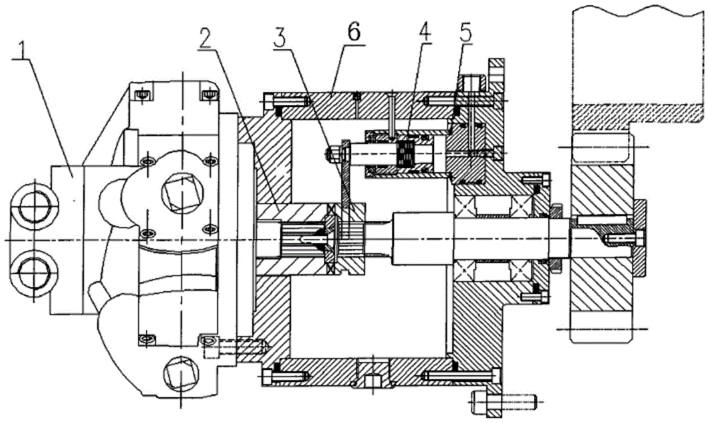
[0012] Such as figure 1 As shown, a new type of clutch includes a motor 1: an outer wall 6, the output shaft of the motor 1 extends into the outer wall 6, the output shaft of the motor 1 is covered with a first clutch device 2, and a hydraulic cylinder 5 is fixedly installed on the inner wall of the rear end of the outer wall. , the movable rod is installed in the hydraulic cylinder 5, the spring 4 is clamped between the movable rod and the hydraulic cylinder 5, the movable rod is connected with the second clutch device 3 through the connecting rod, and the second clutch device 3 is slidingly sleeved on the output shaft of the motor 1 ; The second clutch device 3 can slide back and forth on the motor output shaft, when the spring 4 stretches, the second clutch device 3 slides forward and engages with the first clutch device 2 .

[00...


PUM


Abstract

The invention discloses a novel clutch which comprises a motor. The novel clutch is characterized in that the novel clutch is provided with an outer wall, an output shaft of the motor extends into the outer wall, a first clutch device is sleeved outside the output shaft of the motor, a hydraulic cylinder is fixedly mounted on the inner wall of the rear end of the outer wall, a movable rod is mounted in a hydraulic cylinder, a spring is clamped between the movable rod and the hydraulic cylinder, the movable rod is connected with a second clutch device through a connecting rod, and the second clutch device is slidably sleeved on the output shaft of the motor. The novel clutch can be conveniently controlled in both a power-on state and a power-off state.

Description

technical field [0001] The invention relates to a hydraulic clutch device, in particular to a novel clutch. Background technique [0002] In the past, the hydraulic clutches used in domestic winches and other large-scale mechanical equipment are all traditional structures. Although they can meet the requirements of use, the working state must be controlled by switches or other control devices. For machinery with more complex structures and more work processes It is very inconvenient for the equipment, and after a power failure, the clutch cannot be controlled. Contents of the invention [0003] The technical problem to be solved by the present invention is to provide a new type of clutch that can be conveniently controlled in both power-on and power-off states. [0004] In order to solve the problems of the technologies described above, the technical solution adopted in the present invention is: [0005] A new type of clutch, including a motor: it has an outer wall, the ...

Claims


Application Information

Patent Timeline
IPC IPC(8): F16D29/00
Inventor 易茹
Owner ANHUI IND & TRADE VOCATIONAL TECHN COLLEGE
Why Eureka
Try Eureka