A liquid-draining gas-liquid separator

A technology of gas-liquid separator and exhaust port, which is applied in the direction of refrigeration and liquefaction, refrigeration components, refrigerators, etc., and can solve the problems of single separation principle, large volume, and low separation efficiency

Active Publication Date: 2015-08-12
SHANGHAI JIAO TONG UNIV
View PDF13 Cites 2 Cited by
  • Summary
  • Abstract
  • Description
  • Claims
  • Application Information

AI Technical Summary

Problems solved by technology

[0006] In view of the above-mentioned defects of the prior art, the technical problem to be solved by the present invention is to provide a liquid-draining gas-liquid separator to overcome the shortcomings of the traditional gas-liquid separator, such as large volume, low separation efficiency and single separation principle.

Method used


Image

  • A liquid-draining gas-liquid separator
  • A liquid-draining gas-liquid separator
  • A liquid-draining gas-liquid separator

Examples


Embodiment Construction

[0035] The embodiments of the present invention are described in detail below in conjunction with the accompanying drawings. This embodiment is implemented under the premise of the technical solution of the present invention, and detailed implementation methods and specific operating procedures are provided, but the protection scope of the present invention is not limited to the following the embodiment.

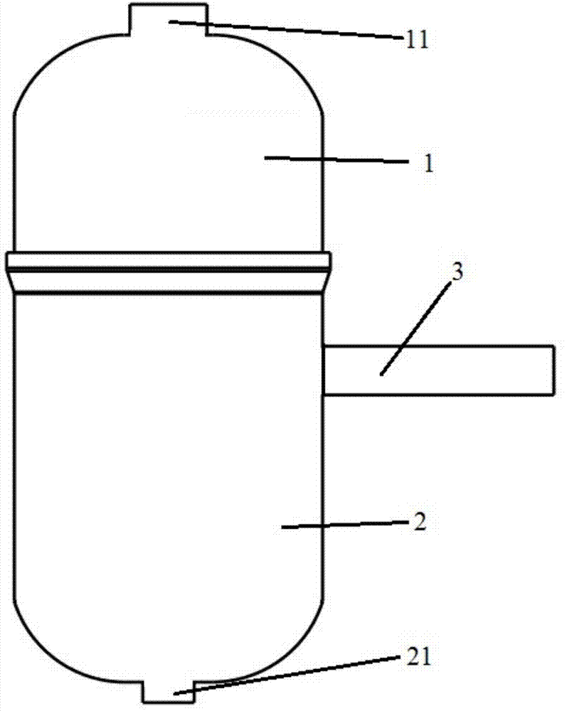
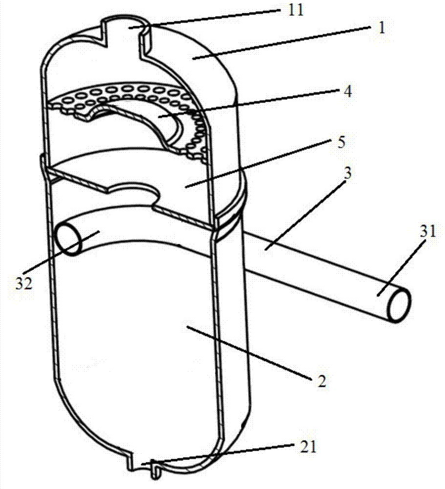
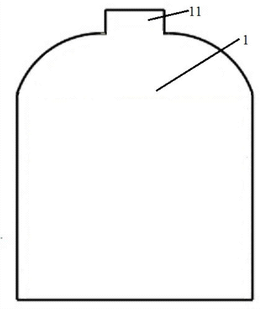
[0036] The front view of the liquid discharge type gas-liquid separator of the present invention is as follows figure 1 As shown, the longitudinal section view is as figure 2 shown. The liquid discharge type gas-liquid separator of the present invention comprises: an upper cylinder 1 , a lower cylinder 2 , a liquid separator 3 , an upper partition 4 and a lower partition 5 . The top of the upper cylinder 1 is provided with an exhaust port 11, and the bottom is open, as image 3 shown. The exhaust port 11 is used to discharge the gas separated by the gas-liquid separator...


PUM


Abstract

The invention discloses a liquid-discharged gas-liquid separator comprises an upper cylinder, a lower cylinder, a liquid separating tube, an upper partition and a lower partition. The top of the upper cylinder is provided with a gas exhausting port used for exhausting separated gas. The bottom of the lower cylinder is provided with a liquid discharging port used for discharging separated liquid. The bottom of the upper cylinder and the top of the lower cylinder are connected in a sealed manner. The liquid separating tube is connected to the lower cylinder, a first end of the liquid separating tube is a straight tube, and a second end is an elbow bent along the inner wall of the lower cylinder. The upper partition is horizontally arranged in the upper cylinder, and a plurality of small holes or filters are annularly arranged in the surface of the inner wall of the upper partition adjacent to the upper cylinder. The lower partition is horizontally arranged at the bottom of the upper cylinder, and the center fo the lower cylinder is provided with an opening or filter. The invention further provides an injection system using the liquid-discharged gas-liquid separator and a cooling system bypassing with the gas inlet of an evaporator. Compared with a conventional gas-liquid separator, the liquid-discharged gas-liquid separator has the advantages that separating efficiency is high, pressure drop is low, and gas-liquid mixture can be separated and respectively discharged.

Description

technical field [0001] The invention relates to a gas-liquid separator in the field of refrigeration air conditioners and heat pumps, in particular to a liquid-draining type gas-liquid separator. Background technique [0002] The gas-liquid separator is a device used for gas-liquid separation. Its functions are: installed at the inlet and outlet of the gas compressor for gas-liquid separation, demisting of the gas phase after the top cooler of the fractionation tower, various gas washing towers, absorption towers The vapor phase defogging and so on. There are many methods of gas-liquid separation, such as gravity sedimentation, centrifugal force separation, baffle separation, packing separation and so on. The most commonly used in the industry are two gas-liquid separation methods: gravity sedimentation separation and centrifugal force separation. [0003] The gravity sedimentation separation method is based on the difference in density between the gas and the liquid. When...

Claims


Application Information

Patent Timeline
Patent Type & Authority Patents(China)
IPC IPC(8): F25B43/00
Inventor 胡记超陈江平韩清梁媛媛黄嘉乐
Owner SHANGHAI JIAO TONG UNIV
Why Eureka
Try Eureka