
A four-leg synchronous hydraulic lifting mechanism

A hydraulic lifting and supporting foot technology, which is applied in the direction of lifting frame and lifting device, can solve the problems of small distance from the ground, cannot meet the requirements of disassembly and assembly of the main landing gear, complex structure, etc., and achieve the effect of simple and reliable operation

Active Publication Date: 2016-02-24
XIAN AIRCRAFT DESIGN INST OF AVIATION IND OF CHINA
View PDF8 Cites 0 Cited by
  • Summary
  • Abstract
  • Description
  • Claims
  • Application Information

AI Technical Summary

Problems solved by technology

[0002] Generally, the hydraulic lifting mechanism adopts the form of "X" type bracket or "><" type bracket. These two types of lifting mechanisms can only realize the lifting function or the lifting and pitching adjustment function. The structure is complex and the function is single, and it is not suitable for the working space in the height direction. small workplace
[0003] In the disassembly and assembly of the main landing gear of a certain type of aircraft, due to the small distance between the lowest point of the main landing gear and the ground (not more than 200mm), the height of the platform of the installation vehicle body is required to be less than 200mm, and the lifting mechanism is required not only to have a lifting function, but also to It has a certain pitch and roll adjustment capability, so the original X-type bracket or "><" type bracket hydraulic lifting mechanism can no longer meet the requirements of the main landing gear disassembly

Method used


Image

  • A four-leg synchronous hydraulic lifting mechanism
  • A four-leg synchronous hydraulic lifting mechanism
  • A four-leg synchronous hydraulic lifting mechanism

Examples


Embodiment Construction

[0018] The specific embodiments of the present invention will be further described below in conjunction with the accompanying drawings.

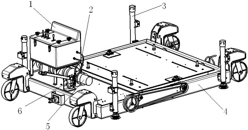
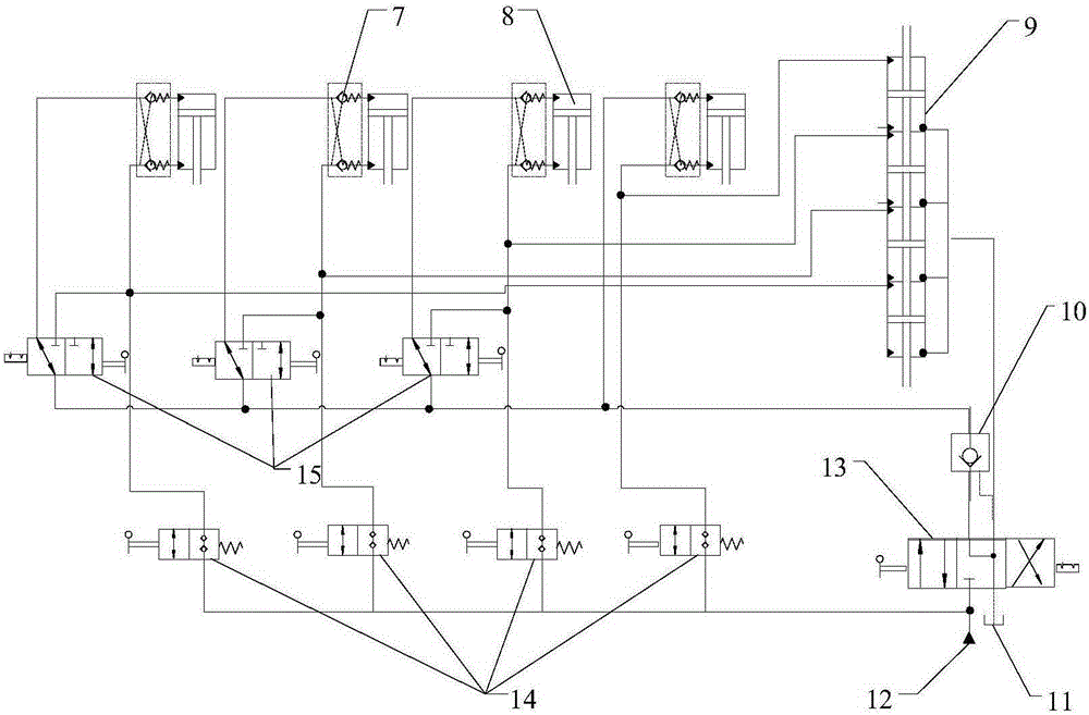
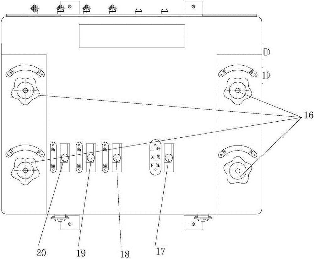
[0019] see figure 1 , figure 2 , a specific embodiment of the present invention mainly includes a hydraulic control box 1, combined conduit 2, hydraulic support feet 3 / 8, car body 4, synchronous cylinder 5 / 9, hand pump 6 / 12, two-way hydraulic lock 7, hydraulic control Check valve 10, fuel tank 11, three-position four-way valve 13, screw switch 14 / 16, two-position three-way valve 15, handle I17, handle IV18, handle III19, handle II20. Among them, the hydraulic control box 1, four hydraulic feet 3, the synchronous cylinder 5 and the hand pump 6 form the lifting mechanism. The main body is installed on the car body 4 of the installation vehicle, and four two-way hydraulic locks 7 are respectively installed on the oil inlet and outlet of each hydraulic foot. , hydraulic control check valve 10, oil tank 11, three-position four-way valve 13, tw...


PUM


Abstract

The invention belongs to the platform lifting technology, and relates to a four-stand-bar synchronous hydraulic lifting mechanism. The four-stand-bar synchronous hydraulic lifting mechanism comprises a mounting vehicle body, four hydraulic stand bars, a hydraulic control box and a synchronous cylinder. The front part and the rear part of the left side frame and the front part and the rear part of the right side frame of the mounting vehicle body are respectively provided with one hydraulic stand bar with an actuator cylinder, the synchronous cylinder comprises four hydraulic chambers and four piston heads connected to a same piston rod, the outlets of the four hydraulic chambers are connected to the four hydraulic stand bars respectively, and the input end of the synchronous cylinder is connected to a hydraulic general oil way through a hydraulic control box containing a hydraulic check valve and a three-position four-way valve. The manual type four-stand-bar synchronous hydraulic lifting mechanism can work in working occasions with small height, the adjustment of the three freedom degrees of the synchronous lifting, the synchronous pitching and the synchronous rolling of the mounting vehicle body can be achieved, operation is convenient, adjusting precision is high, and the four-stand-bar synchronous hydraulic lifting mechanism has good practical application value.

Description

technical field [0001] The invention belongs to platform lifting technology, and relates to a four-leg synchronous hydraulic lifting mechanism. Background technique [0002] Generally, the hydraulic lifting mechanism adopts the form of "X" type bracket or "><" type bracket. These two types of lifting mechanisms can only realize the lifting function or the lifting and pitching adjustment function. The structure is complex and the function is single, and it is not suitable for the working space in the height direction. small workplace. [0003] In the disassembly and assembly of the main landing gear of a certain type of aircraft, due to the small distance between the lowest point of the main landing gear and the ground (not more than 200mm), the height of the platform of the installation vehicle body is required to be less than 200mm, and the lifting mechanism is required not only to have a lifting function, but also to It has a certain pitch and roll adjustment capabi...

Claims


Application Information

Patent Timeline
IPC IPC(8): B66F7/08B66F7/06
Inventor 童丽飞王林王熹
Owner XIAN AIRCRAFT DESIGN INST OF AVIATION IND OF CHINA
Learn More