Telescopic steel truss joint splicing device

A technology for assembling devices and steel truss girders, which is applied in the direction of bridges, bridge construction, erection/assembly of bridges, etc., can solve the problems of manpower and time consumption, inconvenient hoisting, etc., to reduce work links, improve safety, and large work effect of space

Active Publication Date: 2014-03-12
CHINA RAILWAY MAJOR BRIDGE ENG GRP CO LTD +1
View PDF6 Cites 2 Cited by
  • Summary
  • Abstract
  • Description
  • Claims
  • Application Information

AI Technical Summary

Problems solved by technology

Therefore, there are a lot of such temporary operating platforms, which not only consume manpower and time during installation, but also are inconvenient to be hoisted to the next section.

Method used


Image

  • Telescopic steel truss joint splicing device
  • Telescopic steel truss joint splicing device
  • Telescopic steel truss joint splicing device

Examples


Embodiment Construction

[0028] The present invention will be described in further detail below in conjunction with the accompanying drawings and embodiments.

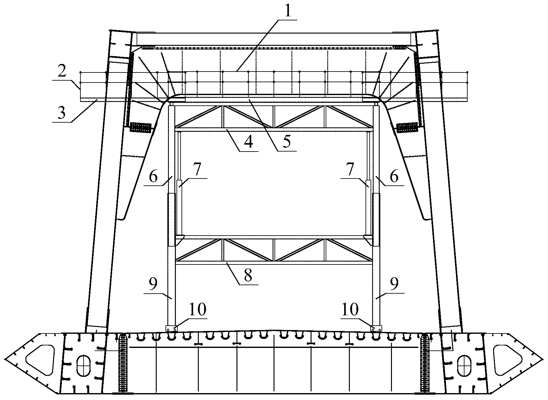
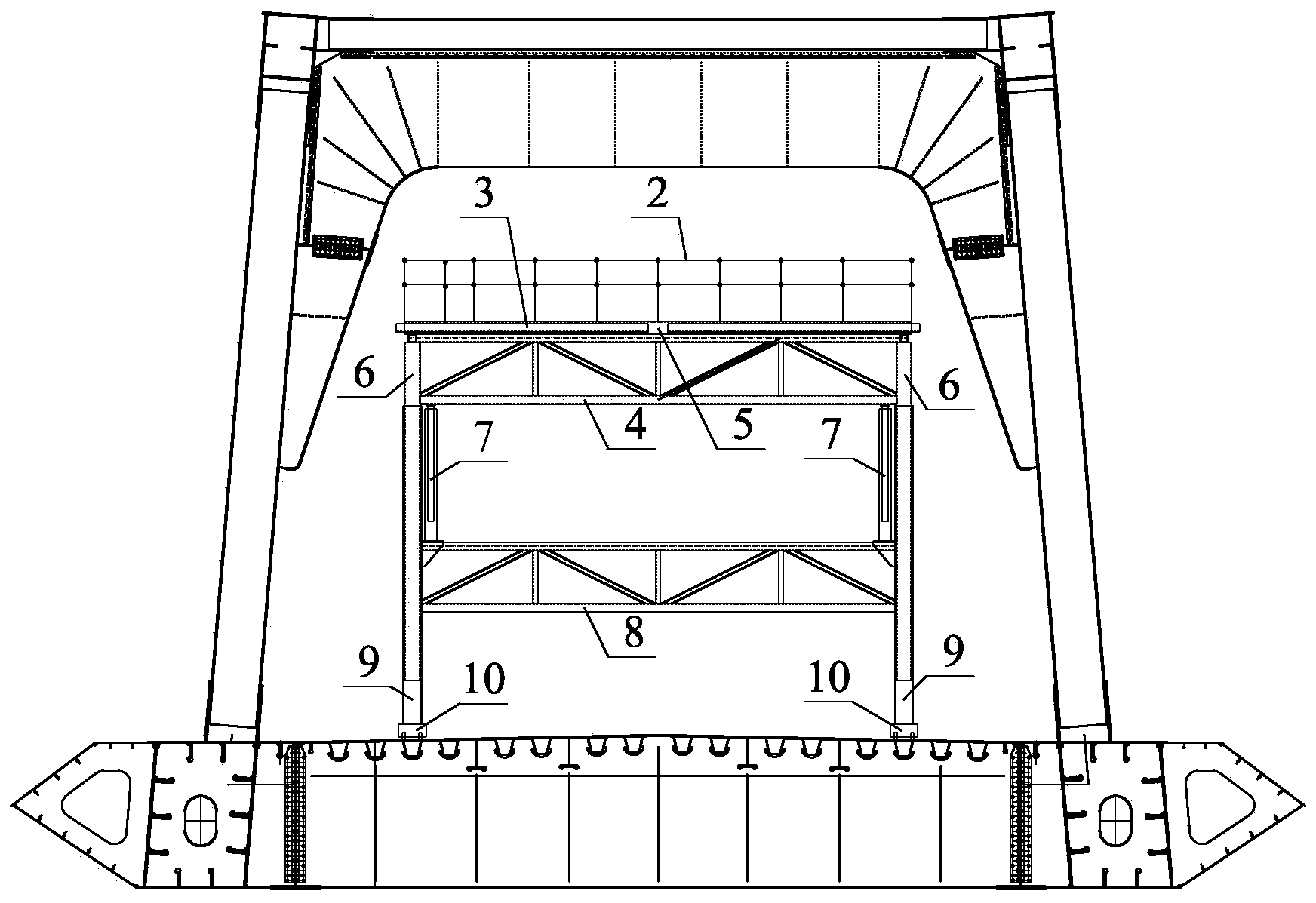
[0029] see figure 1 As shown, the telescopic steel truss beam joint assembly device in the present invention includes a mobile lifting platform and an operating platform, and the operating platform is located on the top of the mobile lifting platform.

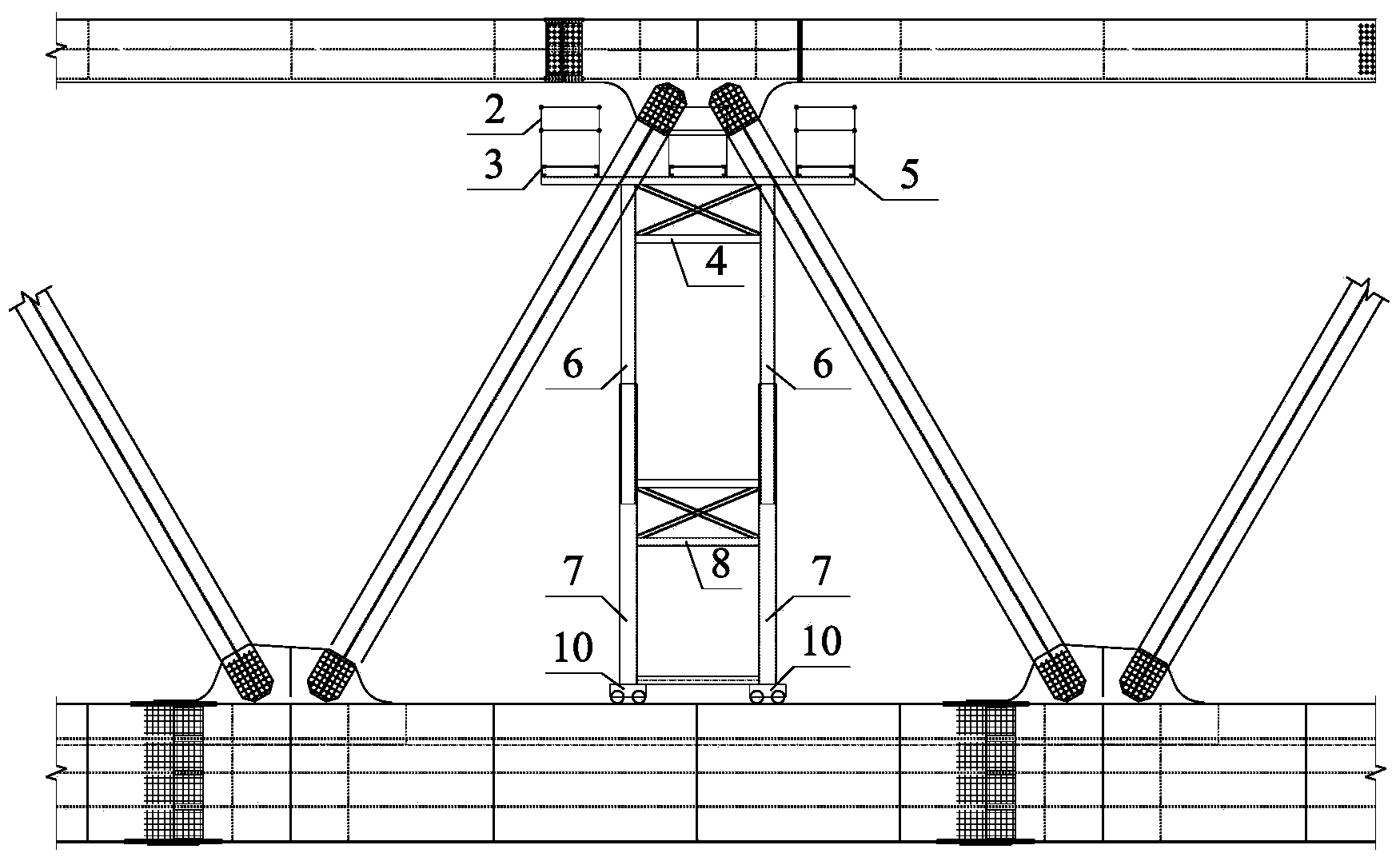
[0030] see figure 1 , figure 2 , image 3 , Figure 4 and Figure 5 As shown, the operating platform includes a fixed platform 5 and a telescopic platform 3 . The fixed platform 5 is fixedly connected to the top of the mobile lifting platform. The fixed platform 5 is a hollow structure. At least one telescopic platform 3 is arranged inside the fixed platform 5. In this embodiment, six telescopic platforms 3 are included. The center of the fixed platform 5 is distributed symmetrically. The opposite sides of telescopic platform 3 are provided with rollers 12, and fixed platform 5 is also ...


PUM


Abstract

The invention discloses a telescopic steel truss joint splicing device, which comprises a movable lifting platform and an operation platform, wherein the operation platform is positioned on the top of the movable lifting platform. The telescopic steel truss joint splicing device is characterized in that the operation platform comprises fixed platforms; the fixed platforms are fixedly connected to the top of the movable lifting platform; the fixed platforms have hollow structures; at least one telescopic platform is arranged inside each fixed platform; rollers are arranged on two opposite sides of each telescopic platform; a plurality of limiting blocks are arranged between each telescopic platform and each fixed platform; each fixed platform is further provided with a power mechanism for controlling the rollers to rotate. The device is safe and reliable, and is convenient to use; the safety of operators can be better protected, and the workload of the operators is reduced.

Description

technical field [0001] The invention relates to the field of bridge construction equipment, in particular to a telescopic steel truss beam joint assembly device. Background technique [0002] When assembling steel truss girders, in order to assemble bolts at the joints of steel truss girders between sections, it is necessary to set up a construction platform at each node position of steel truss girders to provide work space for construction personnel. At present, the common devices for building construction platforms are generally hanging ladders and scaffolding boards. The hanging ladders are welded or bolted by section steel; when the steel truss girders are assembled, the hanging ladders are temporarily fixed to the steel truss girders before the steel truss girders are hoisted. After the steel truss girder is hoisted in place, a scaffolding board is set up between the hanging ladders at the node position of the steel truss girder and fixed to form a temporary simple oper...

Claims


Application Information

Patent Timeline
Patent Type & Authority Applications(China)
IPC IPC(8): E01D21/06
Inventor 李军堂马涛张爱花林明伟郑席晖朱林达吴方明朱佳绪张瀚
Owner CHINA RAILWAY MAJOR BRIDGE ENG GRP CO LTD
Why Eureka
Try Eureka