
Composite steel pipe

A composite steel pipe and pipe body technology, applied in the direction of pipes, rigid pipes, pipes/pipe joints/pipe fittings, etc., can solve the problems of low strength and high cost, and achieve the effect of saving costs and improving the strength of the overall frame

Inactive Publication Date: 2014-03-12
CHANGZHOU LEAP METAL PROD
View PDF0 Cites 4 Cited by
  • Summary
  • Abstract
  • Description
  • Claims
  • Application Information

AI Technical Summary

Problems solved by technology

[0003] In order to overcome the shortcomings of existing stainless steel pipes, such as low strength, high wall thickness and high cost, the present invention provides a composite steel pipe

Method used


Image

  • Composite steel pipe

Examples


Embodiment Construction

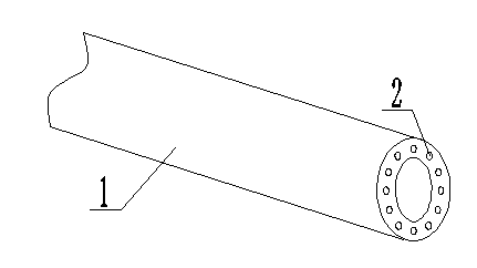
[0010] Such as figure 1 It is a structural schematic diagram of the present invention, a composite steel pipe, including a pipe body 1, and steel bars 2 are arranged in the pipe body 1. The steel bars 2 are evenly inserted in the pipe body 1 and cast into an integral structure with the pipe body 1 .

[0011] Steel bars 2 are arranged in the pipe body 1, and the steel bars 2 are evenly inserted in the pipe body 1 and cast into an integral structure with the pipe body 1, which can add a skeleton to the pipe body 1, which not only improves the overall frame strength of the pipe body 1, but also saves cost.


PUM


Abstract

The invention relates to the technical field of pipeline conveying equipment, in particular to a composite steel pipe. The composite steel pipe comprises a pipe body, and reinforcing steel bars are arranged inside the pipe body. The reinforcing steel bars are evenly inserted into the pipe body, and the reinforcing steel bars and the pipe body are cast to be of an integrated structure. As the reinforcing steel bars are arranged inside the pipe body and are evenly inserted into the pipe body, and the reinforcing steel bars and the pipe body are cast to be of the integrated structure, a framework is added for the pipe body, and not only is the overall framework intensity of the pipe body improved, but also cost is saved.

Description

technical field [0001] The invention relates to the technical field of pipeline transportation equipment, in particular to a composite steel pipe. Background technique [0002] In the chemical, pharmaceutical and other industries, a large number of stainless steel pipes are used for corrosion resistance. In the process of use, in order to make the stainless steel pipe have a certain strength, the pipe wall of the stainless steel pipe is relatively thick, so that the amount of stainless steel pipe is large. , resulting in higher cost and increased cost. Contents of the invention [0003] In order to overcome the disadvantages of low strength, wall thickness and high cost of existing stainless steel pipes, the invention provides a composite steel pipe. [0004] The technical scheme adopted by the present invention to solve the technical problem is: a composite steel pipe, which includes a pipe body, and steel bars are arranged in the pipe body. [0005] According to anothe...

Claims


Application Information

Patent Timeline
Patent Type & Authority Applications(China)
IPC IPC(8): F16L9/04
CPCF16L9/04
Inventor 杨俊杰
Owner CHANGZHOU LEAP METAL PROD
Learn More