Isolation Device

a technology of isolation device and isolation chamber, which is applied in the direction of electrical apparatus casing/cabinet/drawer, cabinet, cabinet details, etc., can solve the problems of poor structural strength and affecting communication

Inactive Publication Date: 2013-09-19
PEGATRON
View PDF4 Cites 4 Cited by
  • Summary
  • Abstract
  • Description
  • Claims
  • Application Information

AI Technical Summary

Benefits of technology

[0007]Accordingly, an embodiment of the present invention provides an isolation device, which includes a frame body and a cover body. The frame body is formed through stamping, and includes a base body and an abutting member. The abutting member is connected at a periphery at a side of the base body....

Problems solved by technology

These seams lead to electric wave intrusion or leakage, affecting the communication.
In addition, the...

Method used


Image

  • Isolation Device
  • Isolation Device
  • Isolation Device

Examples


Embodiment Construction

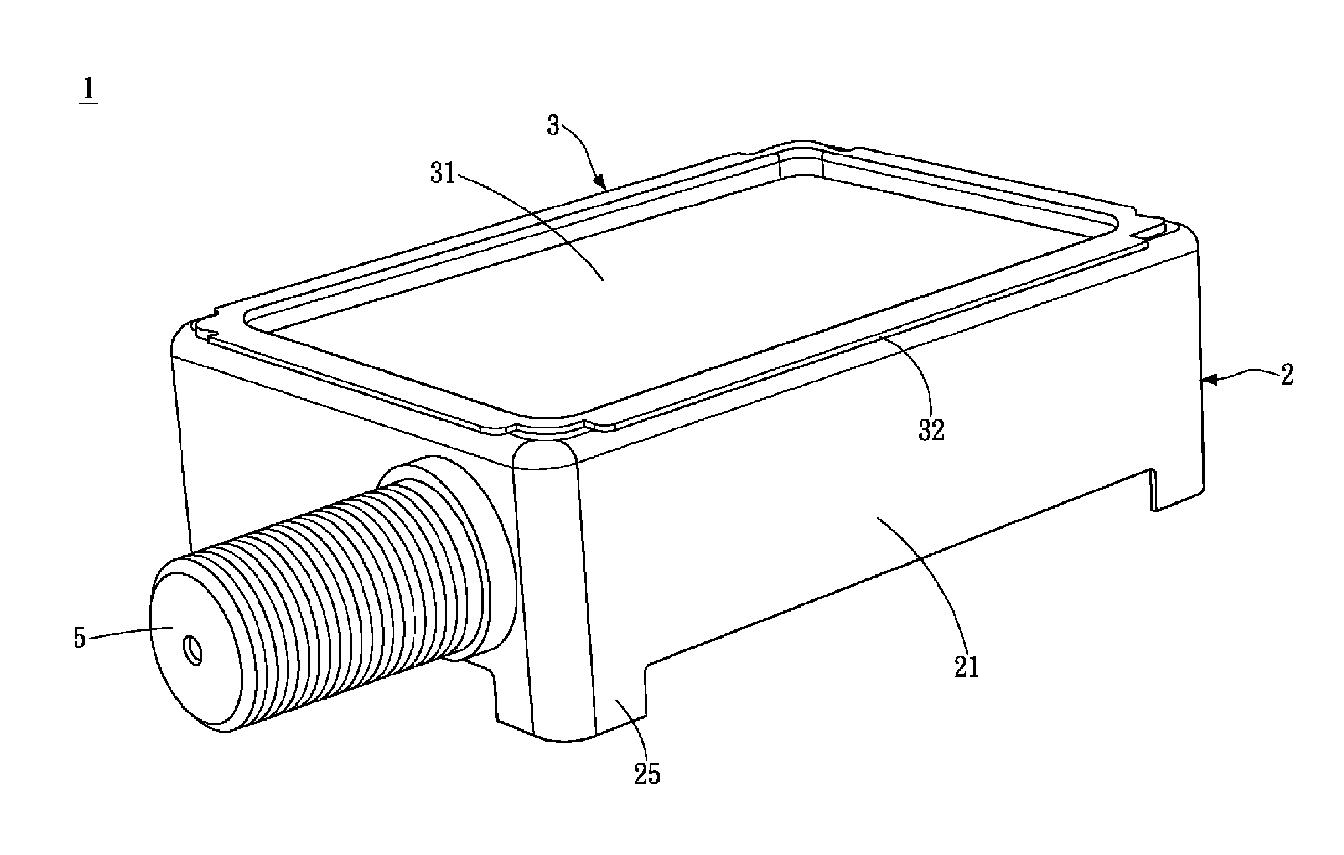
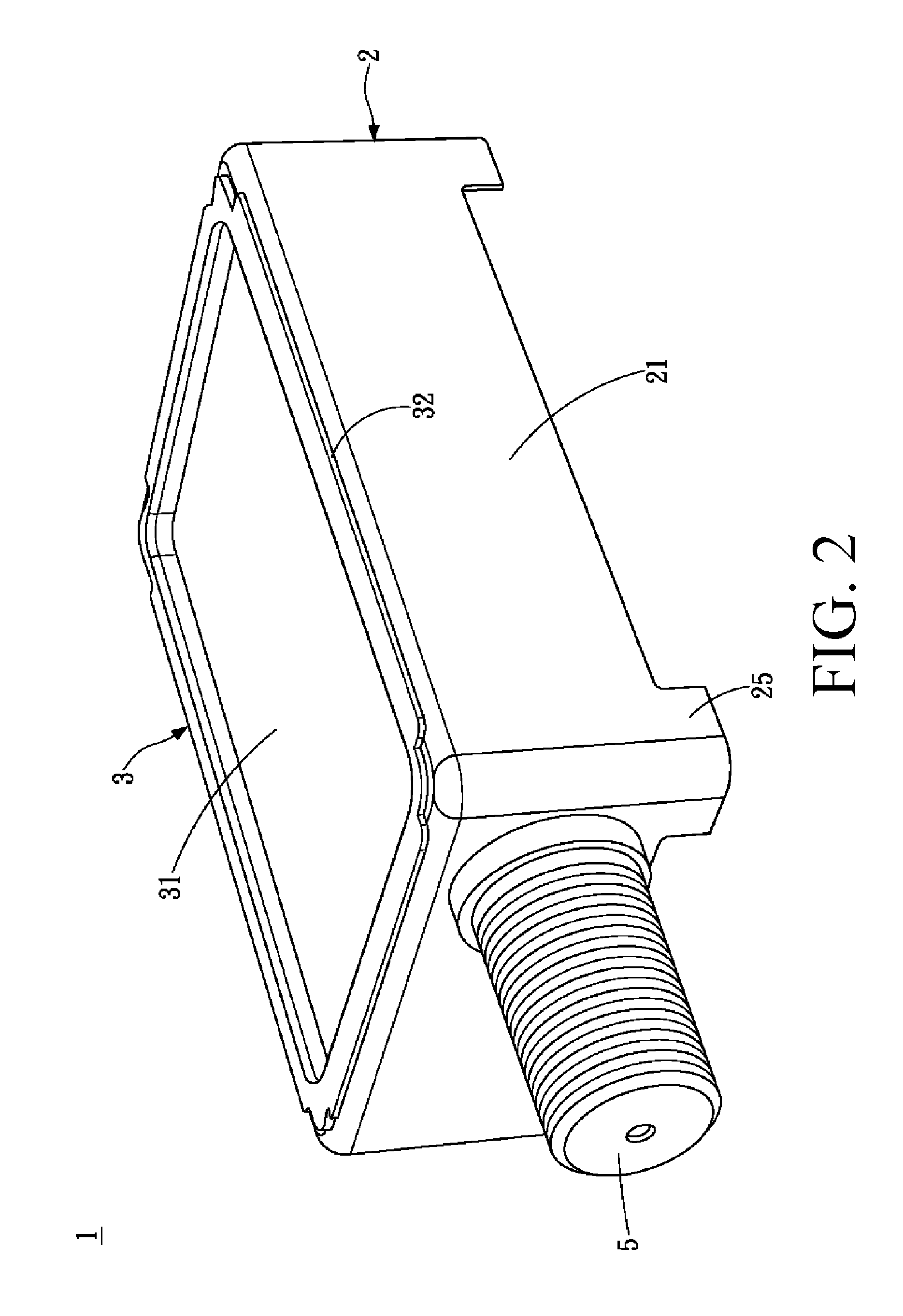
[0017]Please refer to FIG. 2, FIG. 3 and FIG. 4. FIG. 2 is a schematic exterior view of an embodiment of the present invention, FIG. 3 is an exploded schematic view of an embodiment of the present invention, and FIG. 4 is an exploded schematic view from another viewing angle of an embodiment of the present invention. An isolation device 1 according to an embodiment of the present invention includes a frame body 2 and a cover body 3.

[0018]The frame body 2 is made of a metal material, and is formed through stamping. Seen as a whole, the frame body 2 presents a rectangular shape (as shown in FIG. 4). Relevant electronic components may be disposed in the frame body 2, which are not specifically limited herein. The frame body 2 mainly consists of a base body 21 and an abutting member 22. The base body 21 is a hollow body. The abutting member 22 is connected at a periphery at a side of the base body 21, and extends from the periphery towards a central position of the base body 21. The abu...


PUM


Abstract

An isolation device includes a frame body and a cover body. The frame body is formed through stamping, and includes a base body and an abutting member. The abutting member is connected at a periphery at a side of the base body. The cover body includes a main body and a clamping member. The clamping member is connected at a periphery of the main body, and is inserted in the frame body at the cover body. The abutting member abuts tightly against the clamping member, thereby seamlessly integrating the cover body and the frame body. After the cover body is inserted in the frame body, the abutting member abuts tightly against the clamping member, achieving a seamless integration effect.

Description

CROSS-REFERENCES TO RELATED APPLICATIONS[0001]This non-provisional application claims priority under 35 U.S.C. §119(a) on Patent Application No. 101204861 filed in Taiwan, R.O.C. on Mar. 16, 2012, the entire contents of which are hereby incorporated by reference.BACKGROUND OF THE INVENTION[0002]1. Technical Field[0003]The present invention relates to an isolation device, and in particular, to an isolation device that is completely isolated from the outside after being assembled.[0004]2. Related Art[0005]A common isolator is loaded on a printed circuit board (PCB) and used to connect electronic components on the PCB. Please refer to FIG. 1, FIG. 1 is a schematic structural view of a conventional isolator. A conventional isolator A1 consists of an upper cover A11, a bottom frame A12, and a terminal portion A13. The upper cover A11 is a board that forms four side plates A112 at four side edges of a main body A111 through bending, and a plurality of position bumps A113 is provided on an...

Claims


Application Information

Patent Timeline
IPC IPC(8): H05K5/00H05K5/02
CPCH05K5/0004H05K9/006H05K9/0032H05K5/0217
Inventor TSAO, WEI-CHUN
Owner PEGATRON
Why Eureka
Try Eureka