Touch display panel and optical touch panel thereof

A touch panel and optical technology, which is applied in the fields of instruments, computing, electrical and digital data processing, etc., can solve the problems such as the development limitation of optical touch panels and the inability to meet the requirements of thin thickness and narrow borders of touch display panels, etc. achieve the effect of reducing the width

Inactive Publication Date: 2014-03-12
WINTEK CORP
View PDF9 Cites 17 Cited by
  • Summary
  • Abstract
  • Description
  • Claims
  • Application Information

AI Technical Summary

Problems solved by technology

However, since the known optical touch panel needs to have a wider frame and a thicker thickness, it cannot meet the current requirements for the thin thickness and narrow frame of the touch display panel, resulting in the development of the optical touch panel. a big limitation

Method used


Image

  • Touch display panel and optical touch panel thereof
  • Touch display panel and optical touch panel thereof
  • Touch display panel and optical touch panel thereof

Examples


Embodiment Construction

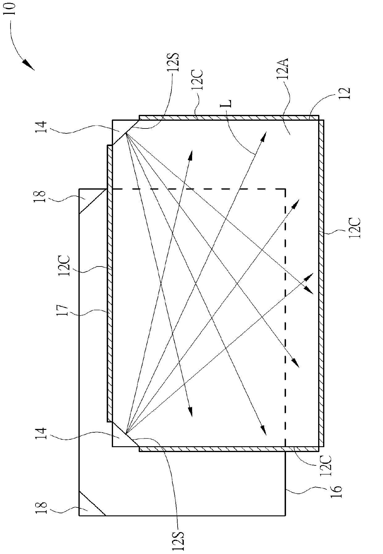
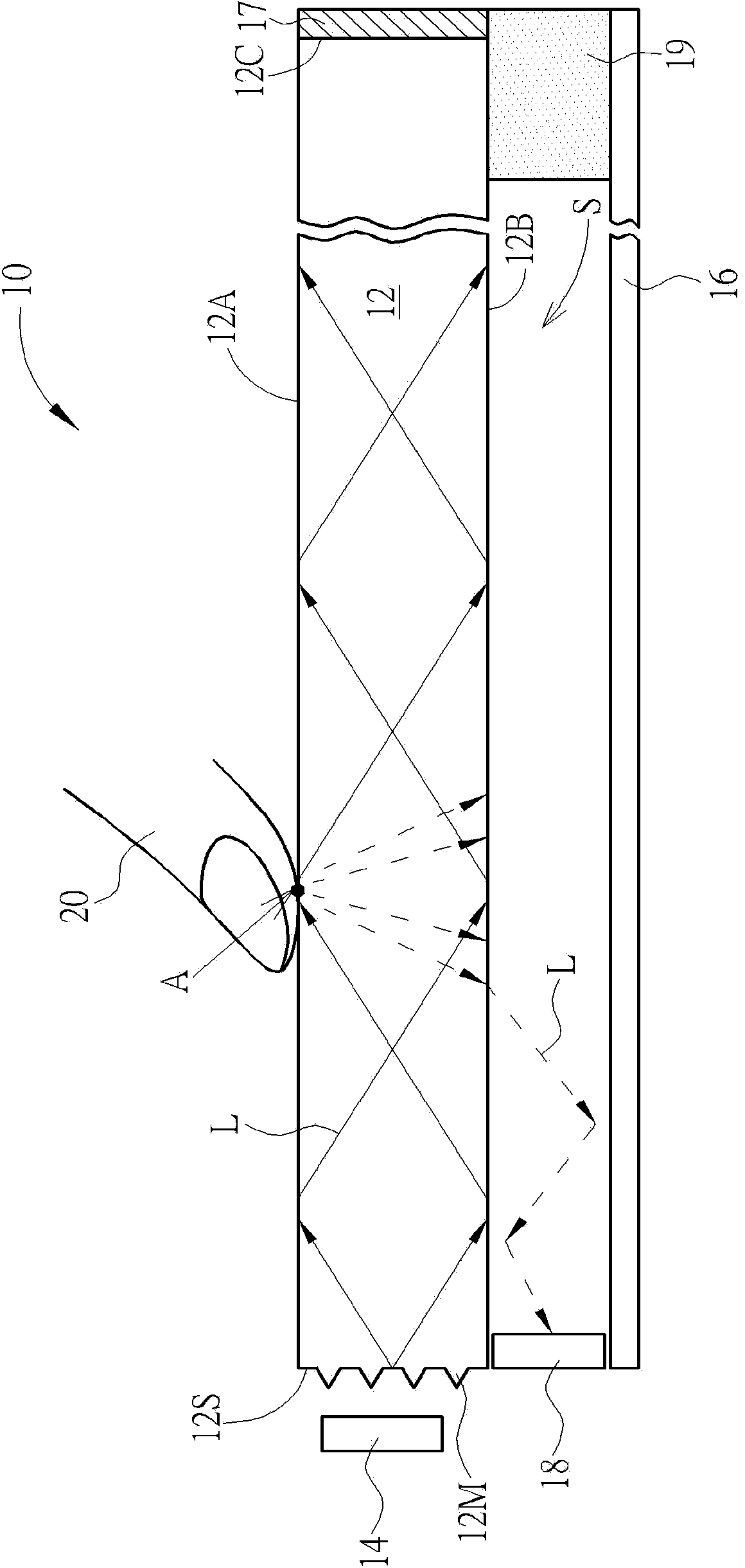
[0089] Please refer to figure 1 and figure 2 . figure 1 shows an exploded schematic view of the optical touch panel of the first preferred embodiment of the present invention, and figure 2 A cross-sectional view of the optical touch panel according to the first preferred embodiment of the present invention is shown. Such as figure 1 and figure 2 As shown, the optical touch panel 10 of this embodiment includes a transparent light guide plate 12 , at least one light emitting device 14 , a bottom reflector 16 and at least one photosensitive device 18 . The transparent light guide plate 12 has an upper surface 12A, a lower surface 12B, at least one side surface 12C and at least one light-incident surface 12S, wherein the upper surface 12A is used for touch input by the user. The material of the transparent light guide plate 12 can be, for example, acrylic or glass, but not limited thereto. The light emitting device 14 faces the light incident surface 12S of the transparen...


PUM


Abstract

An optical touch panel includes a transparent light guide plate, at least one light emitting device, a bottom reflective sheet and at least one light sensing device. The transparent light guide plate has a top surface, a bottom surface and at least one light incident surface. The top surface of the transparent light guide plate is for touch input. The light emitting device faces the light incident surface for emitting a light beam toward the light incident surface. The bottom reflective sheet faces the bottom surface of the transparent light guide plate. A light reflection space is formed between the bottom surface of the transparent light guide plate and the reflective sheet. The light sensing device is disposed on at least one side of the light reflection space for sensing the light beam reflected from the light reflection space.

Description

technical field [0001] The invention relates to a touch display panel and its optical touch panel, in particular to a touch display panel and its optical touch panel using a transparent light guide plate and a bottom reflection sheet as light reflection paths. Background technique [0002] The touch panel has the characteristics of human-computer interaction, and is widely used in external input interfaces of various electronic products. In terms of touch technology, touch panels can be roughly divided into three types: resistive type, capacitive type and optical type. In the application of medium and large display panels, due to the poor process qualification rate and high cost of resistive touch panels and capacitive touch panels, optical touch panels are mainly used as the main development direction. However, since the known optical touch panel needs to have a wider frame and a thicker thickness, it cannot meet the current requirements for the thin thickness and narrow f...

Claims


Application Information

Patent Timeline
Patent Type & Authority Applications(China)
IPC IPC(8): G06F3/042
CPCG06F3/042G06F2203/04109
Inventor 谢宗谚方崇仰林宗贤
Owner WINTEK CORP
Why Eureka
Try Eureka