Supercharge Your Innovation With Domain-Expert AI Agents!

Ultrasound transducer assembly and method of manufacturing the same

一种超声换能器、组件的技术,应用在超声换能器元件,制造这样的超声换能器组件领域,能够解决不容易制造、换能器组件复杂等问题,达到简单制造方式的效果

Active Publication Date: 2014-03-12
KONINKLIJKE PHILIPS NV
View PDF7 Cites 8 Cited by
  • Summary
  • Abstract
  • Description
  • Claims
  • Application Information

AI Technical Summary

Problems solved by technology

However, the transducer assembly disclosed in US2008 / 0315331A1 is quite complex and therefore not easy to manufacture

Method used


Image

  • Ultrasound transducer assembly and method of manufacturing the same
  • Ultrasound transducer assembly and method of manufacturing the same
  • Ultrasound transducer assembly and method of manufacturing the same

Examples


Embodiment Construction

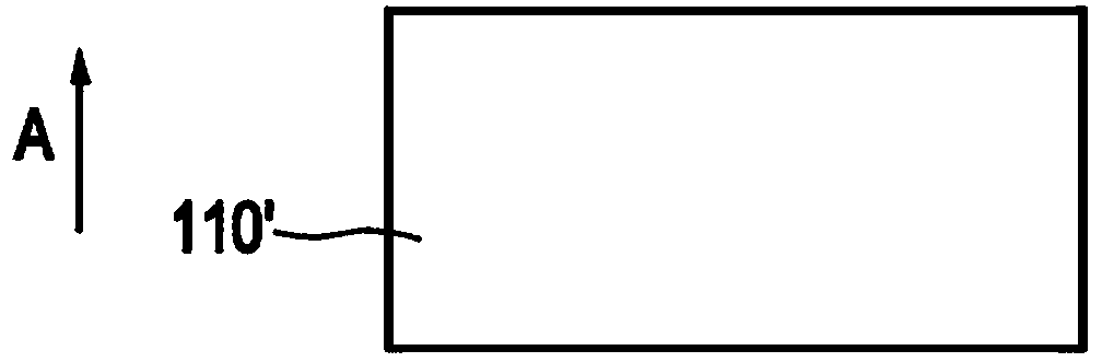
[0027] figure 1 A cross-sectional view of an ultrasound transducer assembly 100 according to an embodiment is shown. The ultrasound transducer assembly 100 comprises ultrasound transducer elements 175 , 175 a for emitting ultrasound waves in a general direction of transmission A . The ultrasound transducer elements 175, 175a may be arranged in a (one-dimensional) row or a (two-dimensional) array. For simplification purposes, the figure 1 Only three of the described ultrasonic transducer elements are illustrated in the cross-sectional view of . It should be understood that there may be any number of additional ultrasound transducer elements arranged in a row or array.

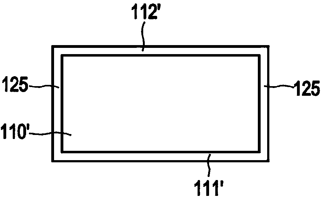
[0028] exist figure 1 In an embodiment of the present invention, each of the ultrasonic transducer elements 175, 175a includes a piezoelectric layer 110, 110a having upper, lower and side surfaces relative to the general direction of transmission A . Each of the upper and lower surfaces of the piezoelectri...


PUM


Abstract

The present invention relates to an ultrasound transducer assembly (100) comprising ultrasound transducer elements (175, 175a) for transmitting ultrasound waves in a general transmission direction (A). Each of, or each of part of, the ultrasound transducer elements (175, 175a) comprises a piezoelectric layer (110, 110a) having a top surface, a bottom surface and a side surface with respect to the general transmission direction (A), as well as a bottom electrode layer (111, 111a) and a top electrode layer (112, 112a). A conductive layer (125) is applied at least partly on the side surface of at least one specific one (110a) of the piezoelectric layers, such that the conductive layer (125) is connected to the top electrode layer (112a) and the bottom electrode layer (111a) of said specific piezoelectric layer (110a).

Description

technical field [0001] The invention relates to an ultrasound transducer assembly comprising an ultrasound transducer element for emitting ultrasound waves in a general direction of transmission. The invention further relates to a method of manufacturing such an ultrasound transducer assembly. Background technique [0002] US2008 / 0315331 Al discloses a transducer assembly with ground connections provided through vias formed in the cMUT array and through an ASIC. The transducer module includes a cMUT transducer sub-array formed on a semiconductor substrate, wherein the front electrode is located over a membrane, and wherein the membrane is suspended over an insulating carrier. Individual units include bottom electrodes for receiving signals from the ASIC circuit unit. Conductive vias are formed in the insulating carrier between adjacent transducer cells to connect the front electrodes to contacts on the cMUT substrate. However, the transducer assembly disclosed in US2008 / 0...

Claims


Application Information

Patent Timeline
Patent Type & Authority Applications(China)
IPC IPC(8): B06B1/06H01L41/047
CPCB06B1/0607H01L41/0475H01L41/29B06B1/0622A61B8/4494Y10T29/42H10N30/875H10N30/06
Inventor W·苏多尔
Owner KONINKLIJKE PHILIPS NV
Features
  • R&D
  • Intellectual Property
  • Life Sciences
  • Materials
  • Tech Scout
  • Unparalleled Data Quality
  • Higher Quality Content
  • 60% Fewer Hallucinations
Learn More