Heat supply metering monitoring system

A monitoring system and monitoring module technology, applied to valve details, engine components, mechanical equipment, etc., can solve the inaccurate positioning of the valve state, the unfavorable overall space of the on-off controller, accurate positioning, replacement of travel switches, and contact travel switch machinery wear and tear

Active Publication Date: 2014-03-19
浙江盾安自控科技有限公司
View PDF10 Cites 3 Cited by
  • Summary
  • Abstract
  • Description
  • Claims
  • Application Information

AI Technical Summary

Problems solved by technology

In practical applications, it is found that the use of contact travel switches to locate the valve state is not conducive to accurate positioning and replacement of travel switches due to the limited overall space of the o

Method used


Image

  • Heat supply metering monitoring system

Examples


Embodiment Construction

[0008] The present invention will be further described below in conjunction with accompanying drawing.

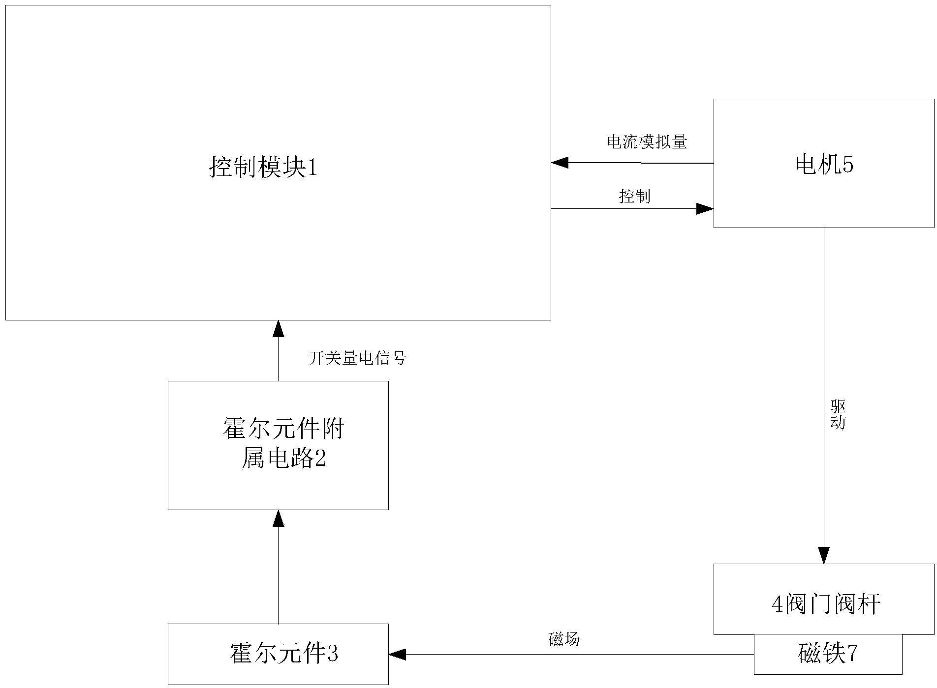
[0009] like figure 1 As shown, the heating metering monitoring system of the present invention includes a monitoring module 1 , a Hall element auxiliary circuit 2 , a Hall element 3 , a valve stem 4 , a motor 5 and a magnet 7 . Wherein, the motor 5 drives the valve stem 4 to provide power for the valve stem 4 . In this embodiment, the monitoring module 1 includes an ARM Cortex-M3 main control circuit, which can monitor and collect signals from the motor 5 and the auxiliary circuit 2 of the Hall element, and send them to the monitoring module 1 for analysis and processing. Structurally, the Hall element 3, the Hall element auxiliary circuit 2 and the ARM Cortex-M3 main control circuit of the monitoring module 1 are sealed in the on-off controller, and the input and output ports of the Hall element auxiliary circuit 2 are connected to the ARM Cortex-M3 M3 main control circu...


PUM


Abstract

The invention discloses a heat supply metering monitoring system which comprises a valve rod of a valve and a driving motor. The heat supply metering monitoring system further comprises a magnet arranged on the valve rod of the valve, a Hall element, a Hall element accessory circuit and a monitoring module used for monitoring the motor. The Hall element and the Hall element accessory circuit are used for sensing the position of the valve rod of the valve and transmitting a signal to the monitoring module. According to the heat supply metering monitoring system, a contact sensing mode is not needed, so that the disadvantages of high mechanical wear, serious mechanical hysteresis, proneness to external vibration, low measurement accuracy, short structural service life and the like caused by a contact sensing mode are avoided, monitoring is more intelligent, and performance is better.

Description

technical field [0001] The invention relates to a monitoring system, in particular to a monitoring system for heat metering. Background technique [0002] The on-off controller is the core component of the heating metering system, and electric valves are usually used at present. When it is in the heating season, the electric valve will automatically switch the valve according to the temperature set by the user and the indoor temperature, and realize energy saving while adjusting the indoor temperature. Therefore, it is necessary to detect the state of the valve during the operation of the on-off controller. Since the opening time of the valve is an important basis for charging the user's heat rate, once the valve state is not judged accurately, the calculation of the heat rate will be inaccurate. [0003] The traditional on-off controller uses a contact travel switch to locate the valve state. In practical applications, it is found that the use of contact travel switches t...

Claims


Application Information

Patent Timeline
IPC IPC(8): F16K37/00F16K31/04
CPCF16K31/04F16K37/0041
Inventor 闫谨林仁干赵明祥王建表
Owner 浙江盾安自控科技有限公司
Why Eureka
Try Eureka