Aperiodic array antenna design method

An array antenna and design method technology, applied in the field of communication, can solve problems such as convergence speed to a local optimal value, difficulty in optimizing results, little consideration of the influence of unit active voltage standing wave ratio array performance, etc., to achieve saving The effect of optimizing time

Active Publication Date: 2014-03-19
XIDIAN UNIV
View PDF4 Cites 28 Cited by
  • Summary
  • Abstract
  • Description
  • Claims
  • Application Information

AI Technical Summary

Problems solved by technology

[0003] However, the unequal spacing array design method has more difficulties compared with the unequal amplitude array design method and unequal phase array design method
First of all, the final element position of the array will have a large change in the entire array size range, and it is difficult to control. The more constraints on the array optimization, the less likely it is to obtain better optimization results; secondly, the distance between array elements Mutual coupling will change as the array element spacing changes, resulting in a large change in the radiation pattern of the element array and the active voltage standing wave ratio (Voltage Standing Wave Ratio, VSWR) of the element.
[0004] In the prior art, there are mainly two methods for the design of unequal-spaced arrays. The first method is mainly aimed at the optimization algorithm itself, and is committed to proposing a faster algorithm with stronger optimization capabilities, without considering the influence of mutual coupling between units or less consideration
Although this method makes a great contribution to the algorithm and takes less time, the result of the comprehensive design is only for the ideal point source, which is difficult to use in actual design
The second method considers the influence of inter-unit mutual coupling, because the change of the array unit spacing will cause

Method used


Image

  • Aperiodic array antenna design method
  • Aperiodic array antenna design method
  • Aperiodic array antenna design method

Examples


Embodiment Construction

[0023] In order to make the purpose, technical solutions and advantages of the embodiments of the present invention clearer, the technical solutions in the embodiments of the present invention will be clearly and completely described below in conjunction with the drawings in the embodiments of the present invention. Obviously, the described embodiments It is a part of embodiments of the present invention, but not all embodiments. Based on the embodiments of the present invention, all other embodiments obtained by persons of ordinary skill in the art without creative efforts fall within the protection scope of the present invention.

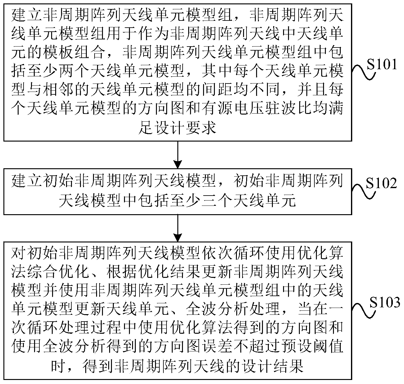
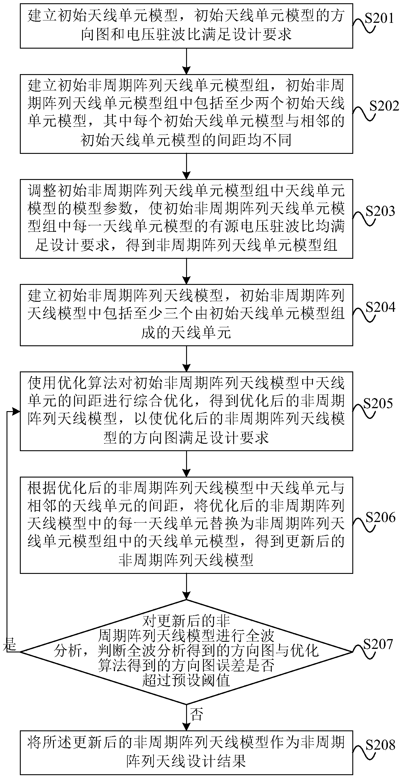
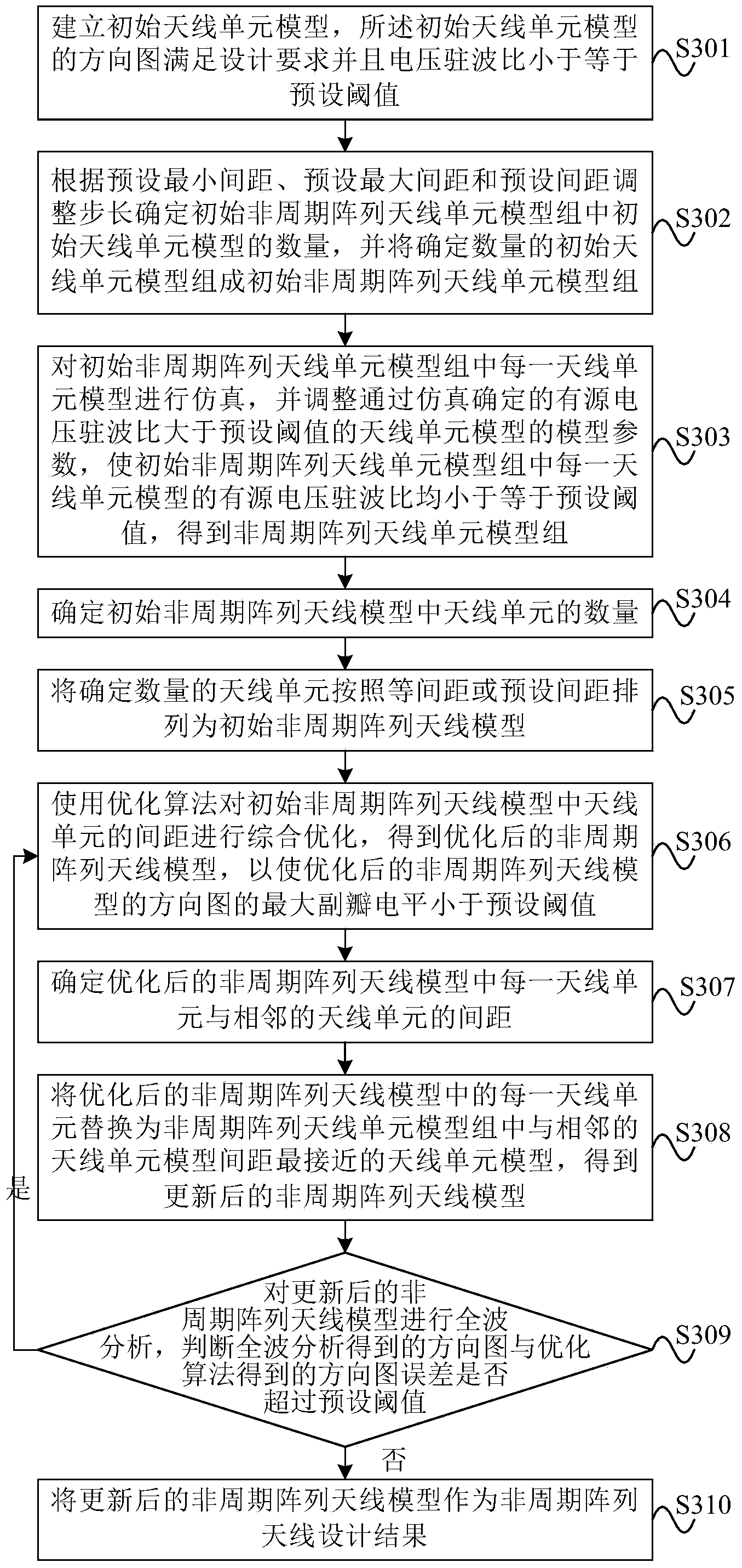
[0024] An array antenna is formed by arranging a plurality of antenna units in a certain arrangement, and the radiation patterns of all the antenna units in the array together form the radiation pattern of the array antenna. The aperiodic array antenna means that the arrangement of the antenna elements in the array antenna is aperiodic. Since the ...


PUM


Abstract

The invention provides an aperiodic array antenna design method. The method comprises the steps as follows: establishing an element model group of aperiodic array antenna, wherein the element model group comprises at least two antenna element models, and the distances between each antenna element model and other antenna element models adjacent to the antenna element model are different, and the directional diagram and the active voltage standing wave ratio of the antenna element model can meet design demands; establishing an initial aperiodic array antenna model, wherein the initial aperiodic array antenna model comprises at least three antenna elements; conducting the comprehensive optimization on the initial aperiodic array antenna model according to the optimization algorithm, updating the aperiodic array antenna model according to the result of optimization, updating antenna elements by using the antenna element models, and carrying out full wave analysis and process on the initial aperiodic array antenna model in sequence; when the error between a directional diagram obtained according to the optimization algorithm and a directional diagram obtained according to full wave analysis during once circular treating process is not larger than a preset threshold value, the design result of the aperiodic array antenna is obtained.

Description

technical field [0001] The present invention relates to communication technology, in particular to a method for designing an aperiodic array antenna. Background technique [0002] The comprehensive design of the array antenna can usually be realized by three methods, which are changing the excitation amplitude of the array elements, changing the excitation phase of the array elements and changing the spacing between the array elements. However, for the unequal-amplitude array design method that changes the excitation amplitude of the array unit, there will usually be a larger amplitude excitation ratio, and the use of unequal-amplitude excitation will also affect the total radiation of the array because the array unit does not work at the maximum power Power; For the unequal-phase array design method of changing the excitation phase of the array elements, more array elements need to be used compared with the unequal-amplitude array, and an expensive phase shifter is required...

Claims


Application Information

Patent Timeline
IPC IPC(8): G06F17/50H01Q21/00
Inventor 陈蕾张天龄余剑峰王超史小卫
Owner XIDIAN UNIV
Why Eureka
Try Eureka