A wafer working method for monitoring defect conditions of multi-cavity devices

A multi-chamber and wafer technology, applied in semiconductor/solid-state device testing/measurement, electrical components, circuits, etc., can solve difficult monitoring problems and achieve fast and accurate judgment

Active Publication Date: 2014-03-19
SHANGHAI HUALI MICROELECTRONICS CORP
View PDF7 Cites 6 Cited by
  • Summary
  • Abstract
  • Description
  • Claims
  • Application Information

AI Technical Summary

Problems solved by technology

[0007] In view of the above existing problems, the present invention discloses a wafer operation method for monitoring the defect status of multi-chamber equipment, so as to overcome the difficulty in the prior art to effecti

Method used


Image

  • A wafer working method for monitoring defect conditions of multi-cavity devices
  • A wafer working method for monitoring defect conditions of multi-cavity devices
  • A wafer working method for monitoring defect conditions of multi-cavity devices

Examples


Embodiment 1

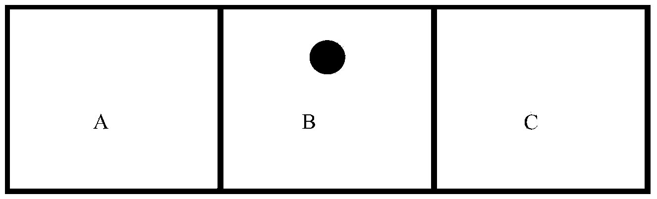
[0036] Such as Figure 8 and Figure 9As shown, this embodiment relates to a wafer operation method for monitoring the defect status of multi-chamber equipment, which is applied to a production execution system. The production execution system includes several processes, and each process includes multi-chamber equipment and defect conditions. Inspection site, set the rules for sampling wafers at the defect detection site, and save the rules for sampling wafers at the defect detection site and the cavity information in all multi-chamber equipment to the central server in advance, where the multi-chamber equipment in process A has No. 1, No. 2... No. 10 have a total of 10 operable cavities. The defect detection station of process A is to conduct random inspection on the 1st, 2nd, 3rd, 10th, 11th, and 24th wafers to be sampled. Wafers 1, 2, 3, 10, 11, and 24 are wafers to be sampled. When the first batch of wafer products to be processed arrives at process A, the central server ...

Embodiment 2

[0039] This embodiment is roughly the same as Embodiment 1. The difference is that in Embodiment 1, wafers to be sampled are randomly allocated to different chambers of the multi-chamber equipment in the current process. In this embodiment, wafers to be sampled are allocated sequentially. to the different chambers of the multi-chamber equipment of the current process.

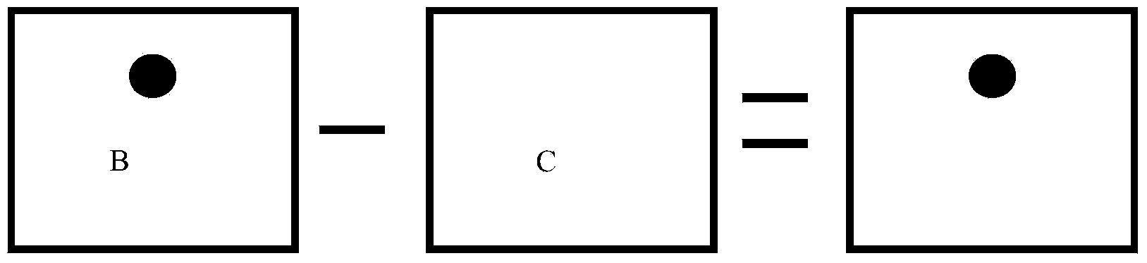
[0040] This embodiment is specifically as follows: when the first batch of wafer products to be processed arrives at process A, the central server issues an instruction to order the wafers 1, 2, 3, 10, 11, and 24 of the first batch of wafers to be processed in sequence. Assign to chambers 1-6 for operation, and the central server will record the information currently assigned, and judge whether each chamber of the multi-chamber equipment in process A is assigned to the wafer to be sampled, and if so, Then carry out the multi-cavity equipment operation of process A. If this embodiment is No, it is necessary to w...


PUM


Abstract

The invention discloses a wafer working method for monitoring defect conditions of multi-cavity devices, and is applied to a production execution system. The method comprises the following steps: rules of detecting wafers in a defect detect station and cavity information of all multi-cavity devices are saved in a central server; when working wafers reach any working procedure, the central server determines to-be-selected-and-detected wafers in the wafers and controls the multi-cavity devices in the present working procedure to distribute the to-be-selected-and-detected wafers into different cavities of the multi-cavity devices to carry out working, and the present distribution and working information are recorded; the defect detect station in the present working procedure carries out defect detection on the to-be-selected-and-detected wafers after working; and according to defect detection results, defect conditions of the multi-cavity devices in the present working procedure are monitored. Through the adoption of the technical scheme of the present invention, effective monitoring can be carried out on the defect conditions of the plurality of cavities of working procedure devices in a production execution system, and at the same time, reasons for occurrence of defects of the wafers can be rapidly and accurately determined.

Description

technical field [0001] The invention relates to the technical field of semiconductor manufacturing, in particular to a wafer operation method for monitoring defect conditions of multi-cavity equipment. Background technique [0002] The advanced integrated circuit manufacturing process generally includes hundreds of steps, and a small error in any link will lead to the failure of the entire chip, especially as the critical size of the circuit continues to shrink, the requirements for process control become stricter, so In the production process, in order to find and solve problems in time, expensive optical and electronic defect detection equipment is equipped to detect products online. Regardless of whether it is optical or electronic defect detection, the basic principle of its work is to obtain the signals of several chips through the equipment, and then compare the data, such as figure 1 It is represented as three adjacent chips. By collecting the graphic data of the thr...

Claims


Application Information

Patent Timeline
IPC IPC(8): H01L21/66
CPCH01L22/12H01L22/20
Inventor 倪棋梁王凯陈宏璘龙吟
Owner SHANGHAI HUALI MICROELECTRONICS CORP
Why Eureka
Try Eureka