
A kind of piezoelectric bimorph and its preparation method

A piezoelectric bimorph and bimorph technology, which is applied in piezoelectric/electrostrictive/magnetostrictive devices, circuits, electrical components, etc. device failure and other problems, to achieve the effects of stable and reliable working process, reduced diffusion depth, and long service life

Active Publication Date: 2018-05-08
CHONGQING ZHONGLEI SCI & TECH
View PDF1 Cites 0 Cited by
  • Summary
  • Abstract
  • Description
  • Claims
  • Application Information

AI Technical Summary

Problems solved by technology

The middle bonding layer of the piezoelectric bimorph prepared by the bonding process is a non-conductor and has a certain thickness. Once the process is not properly controlled, the thickness of the bonding layer will be uneven, resulting in a weak electrical signal (generally 0) generated by the piezoelectric crystal. -1V) sometimes fails to transmit, eventually causing the piezoelectric device to fail

Method used

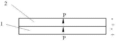
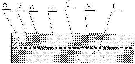

Image

  • A kind of piezoelectric bimorph and its preparation method
  • A kind of piezoelectric bimorph and its preparation method
  • A kind of piezoelectric bimorph and its preparation method

Examples


Embodiment 1

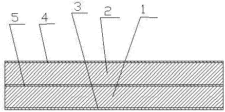
[0024] The piezoelectric bimorph of this embodiment has a wafer structure, the upper and lower piezoelectric bodies use the same soft PZT material, and the electrode layer uses silver-palladium electrodes. The schematic diagram of the structure is as follows figure 1 As shown, it includes a lower piezoelectric body 1, an upper piezoelectric body 2, a lower conductive electrode layer 3, an upper conductive electrode layer 4, and a common electrode layer 5. The lower piezoelectric body 1 and the upper piezoelectric body 2 have the same size.

[0025] The preparation method of the piezoelectric bimorph in the present embodiment comprises the following steps:

[0026] Step 1: Grind the sintered lower piezoelectric body 1 and upper piezoelectric body 2 respectively, wash them with ultrasonic water, ultrasonic alcohol and ultrasonic acetone respectively, and dry them at 120°C for use;

[0027] Step 2: Print silver-palladium paste on both sides of the lower piezoelectric body 1 and ...

Embodiment 2

[0034] The piezoelectric bimorph of this embodiment has a rectangular structure, the upper and lower piezoelectric bodies are all made of the same hard PZT material, and the electrode layer is made of silver electrodes; the structure includes a lower piezoelectric body 1, an upper piezoelectric body 2, a lower conductive electrode layer 3, The upper conductive electrode layer 4, the common electrode layer 5, and the lower piezoelectric body have the same size as the upper piezoelectric body.

[0035] The preparation method of the piezoelectric bimorph in the present embodiment comprises the following steps:

[0036] Step 1: Grind the sintered lower piezoelectric body 1 and upper piezoelectric body 2 respectively, wash them with ultrasonic water, ultrasonic alcohol and ultrasonic acetone respectively, and dry them at 120°C for use;

[0037] Step 2: Print silver paste on the two sides of the lower piezoelectric body 1 and the upper piezoelectric body 2 respectively by printing p...


PUM

PropertyMeasurementUnit
sizeaaaaaaaaaa
diameteraaaaaaaaaa
thicknessaaaaaaaaaa

Abstract

The invention relates to a piezoelectric bimorph and a preparation method thereof. The piezoelectric bimorph includes a lower piezoelectric body, an upper piezoelectric body, a lower conductive electrode layer, an upper conductive electrode layer, and a common electrode layer. The lower piezoelectric body and the upper piezoelectric body are composed of PZT piezoelectric materials. The electric body and the upper piezoelectric body are connected through a common electrode layer sintered under high temperature pressure. The preparation method of the piezoelectric bimorph involves printing electrodes on the surface of the upper and lower piezoelectric bodies, drying and sintering the common electrode layer under a certain pressure to realize high-temperature pressure sintering. . The invention solves the insulation problem of the adhesive layer in the piezoelectric bimorph, and has the characteristics of stable and reliable working process and long service life.

Description

technical field [0001] The invention belongs to the technical field of piezoelectric ceramic drivers and sensors, in particular to a piezoelectric bimorph and a preparation method thereof. Background technique [0002] With the development of electronic technology, the bimorph type piezoelectric driver or sensor formed by using the direct piezoelectric effect or inverse piezoelectric effect of piezoelectric technology can be used as the core control element of intelligent control. Piezoelectric pumps for conveying gas and liquid mostly use simply supported beam bimorphs, which use the inverse piezoelectric effect of the piezoelectric chip to drive the flexural vibration of the entire piezoelectric drive vibrator to change the volume formed between the piezoelectric drive vibrator and the housing. The volume of the chamber realizes continuous negative pressure suction and pressurized discharge of gas and liquid. The piezoelectric valve also uses a cantilever beam bimorph. Un...

Claims


Application Information

Patent Timeline
Patent Type & Authority Patents(China)
IPC IPC(8): H01L41/273H01L41/083
Inventor 王素贞
Owner CHONGQING ZHONGLEI SCI & TECH
Learn More