Transmission line dynamic loss measurement system and method

A transmission line and dynamic loss technology, which is applied in the direction of measurement devices, electric power measurement and electric variable measurement by applying digital technology, can solve problems such as current generation and power loss, achieve accurate measurement, solve simultaneity, and solve electromagnetic interference problem effect

Inactive Publication Date: 2011-09-07
NORTH CHINA ELECTRIC POWER UNIV (BAODING)
View PDF2 Cites 17 Cited by
  • Summary
  • Abstract
  • Description
  • Claims
  • Application Information

AI Technical Summary

Problems solved by technology

[0006] When the circuit is in normal operation, the spatial position of each phase ground wire and the transmission wire is asymmetrical. Although the voltage and current on each phase transmission wire are basically balanced, there will still be electrostatic induction components and electromagnetic induction components on the ground wire at the same time, that is, induced voltage , if there is a current channel between the ground wire and the earth, current will be generated, resulting in power loss. When the system fails, the induced voltage on the ground wire will be greater, and the wire is directly between the double ground wire and the ground wire and the ground wire. Form a larger circulation and its power loss

Method used


Image

  • Transmission line dynamic loss measurement system and method
  • Transmission line dynamic loss measurement system and method
  • Transmission line dynamic loss measurement system and method

Examples


Embodiment Construction

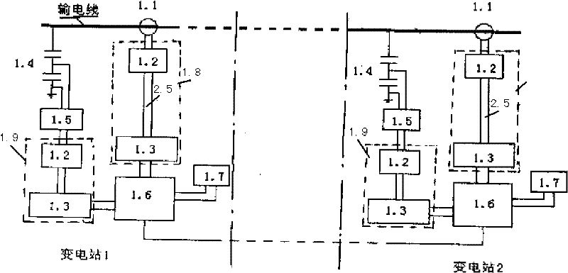
[0022] A system and method for dynamic loss measurement of transmission lines are proposed. The present invention will be described in further detail below in conjunction with the accompanying drawings.

[0023] figure 1 Shown is the principle structure diagram of the transmission line dynamic loss measurement system. The voltage and current acquisition system and the industrial computer unit are respectively installed at the head end (substation 1) and the end (substation 2) of the transmission line. At the end of the substation 1, there is zero magnetic flux The current transformer 1.1 is connected to the first OPDL photoelectric link system 1.8 composed of the photoelectric remote module 1.2 connected to the photoelectric local module 1.3 through the optical fiber composite insulator 2.5, and the photoelectric local module 1.3 of the first OPDL photoelectric link system 1.8 is connected with the data The industrial computer 1.6 of the acquisition card, and the industrial c...


PUM


Abstract

The invention discloses a transmission line dynamic loss measurement system and a transmission line dynamic loss measurement method, which belong to the technical field of high-voltage transmission line detection. The transmission line dynamic loss measurement system is based on global positioning system (GPS) clock pulse synchronous triggering, and comprises voltage and current acquisition systems and industrial personal computer units which are arranged at substations at the two ends of a transmission line respectively. Voltage and current signals are extracted by utilizing a zero-flux current transformer, and are transmitted to a data acquisition card in an industrial personal computer by an optically powered data link (OPDL) photoelectric link system, the data acquisition card is triggered by using GPS clock pulses to realize the synchronism of voltage and current acquisition at the front and tail ends of the line, and the power of the two ends of the line is calculated by using an instantaneous power method to obtain the dynamic loss of the whole transmission line. The simultaneous acquisition of voltage and current at the two ends of the line is realized, a numerical value of the synchronization accuracy is less than 0.1 microsecond, high measurement accuracy and convenience of operation are ensured, the problem of insulation is solved, and potential safety hazards are avoided.

Description

technical field [0001] The invention belongs to the technical field of high-voltage transmission line detection, and in particular relates to a dynamic loss measurement system and method of a transmission line, in particular to a dynamic loss measurement system of a transmission line based on GPS clock pulse synchronous triggering and an ultra-low voltage between two substations. / UHV transmission line dynamic loss measurement method, which is suitable for measuring the economy of transmission lines. Background technique [0002] The dynamic loss of transmission lines mainly includes resistance loss, corona loss, leakage loss of insulators and loss on the ground, etc. There are few reports on dynamic loss measurement of transmission lines at home and abroad, and most of them focus on the research of corona loss of no-load conductors. [0003] The transmission wire is not a superconductor, and there is a certain wire resistance. When the load current flows on the transmissio...

Claims


Application Information

Patent Timeline
Patent Type & Authority Applications(China)
IPC IPC(8): G01R27/26G01R21/133
Inventor 刘云鹏黄宗君律方成万启发谢雄杰尤少华朱雷
Owner NORTH CHINA ELECTRIC POWER UNIV (BAODING)
Why Eureka
Try Eureka