Method for reforming carbonaceous materials

a carbonaceous material and carbonaceous technology, applied in vacuum evaporation coating, nuclear engineering, therapy, etc., can solve the problems of low melting point, low efficiency, and difficult purpose-based processing, and achieve the effect of small duty ratio, input energy and pulse width

Inactive Publication Date: 2008-09-11
NGK INSULATORS LTD
View PDF8 Cites 2 Cited by
  • Summary
  • Abstract
  • Description
  • Claims
  • Application Information

AI Technical Summary

Benefits of technology

[0016]The present inventors found that physical properties of a carbonaceous material can be reformed without greatly changing the minute shape of a surface of the carbonaceous material, by irradiati

Problems solved by technology

When the metal surface smoothing methods as described above are applied thereto, however, purpose-based processing is difficult because the minute shape of the surface is seriously affected.
An organic thin f

Method used


Image

  • Method for reforming carbonaceous materials
  • Method for reforming carbonaceous materials
  • Method for reforming carbonaceous materials

Examples


example 1

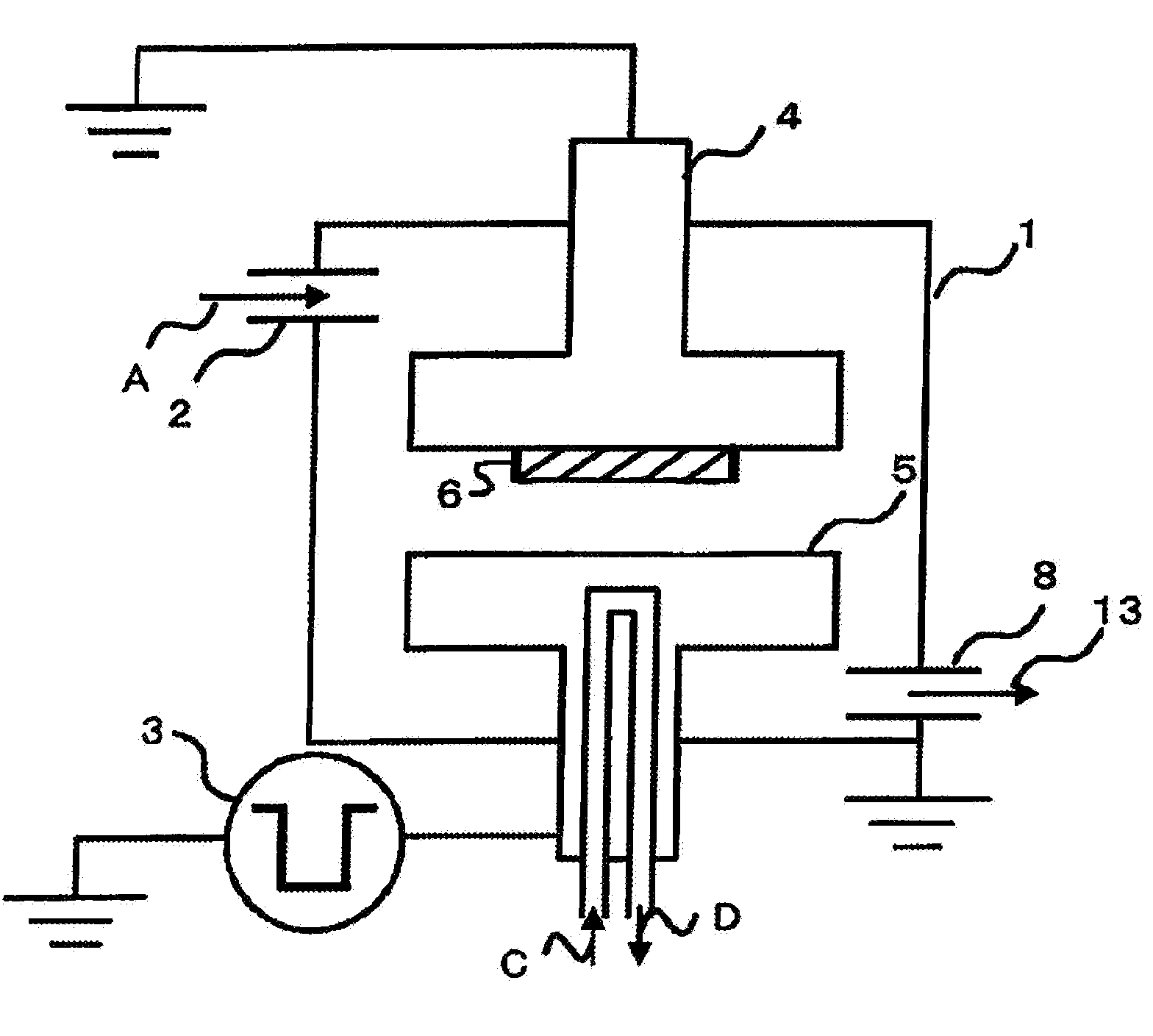
[0055]An amorphous carbon (diamond-like carbon: DLC) film 6 was set on an earth potential of a vacuum apparatus by the method described in reference to FIG. 2. The DLC film is composed of a material comprising 70% carbon and 30% hydrogen. Nitrogen gas was supplied into the vacuum apparatus and controlled to a pressure of 1 Pa. A DC pulse of −10 kV with pulse width 0.5 μsec and duty ratio 0.5 was applied to a cathode electrode 4 opposed to the earth potential, and the amorphous carbon film was irradiated with the electron beam for 2 hours with an input energy of 0.0013 J / cm2. A half of the carbon film as a sample was masked so as not to be irradiated with the electron beam, forming a non-irradiated surface as a comparative example. The remaining half of the carbon film was exposed and irradiated with the electron beam.

[0056]The surface roughness Ra of the film after the irradiation with electron beam was 0.1 to 1.0 nm both in the irradiated surface and in the non-irradiated surface w...

example 2

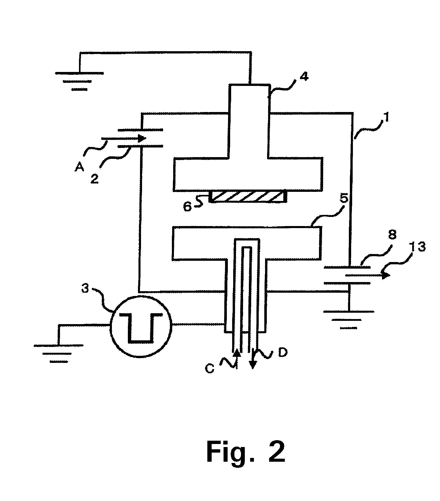
[0059]A photoresist mask 6 was treated by the method described in reference to FIG. 3. The photoresist (OFPR-800) used has a carbon content of about 50%. The carbon content of the photoresist corresponds to the value after baking. A silicon wafer 6 coated with the photoresist mask was set on an anode electrode 5 in the vacuum apparatus. A half of the photoresist of the wafer was masked with a slide glass to form an electron beam non-irradiated surface. The remaining half was taken as an irradiated surface. The chamber was used as a cathode electrode (earth potential). Argon gas was supplied into the vacuum chamber and controlled at a pressure of 2.0 Pa. A DC pulse voltage of +10.5 kV with pulse width 0.2 μsec (200 nsec) and duty ratio 0.04 was applied to the anode electrode, and the photoresist was irradiated with the electron beam for 10 minutes in a condition of input energy 0.00020 J / cm2.

[0060]The surface roughness Ra of the film before the irradiation with the electron beam was ...


PUM

PropertyMeasurementUnit
Fractionaaaaaaaaaa
Fractionaaaaaaaaaa
Timeaaaaaaaaaa

Abstract

A carbonaceous material containing 30 atm % or more of carbon atom is reformed. The reforming is carried out by applying a DC pulse voltage to an electrode set within a chamber to generate an electron beam, and by then irradiating a surface of the carbonaceous material with the electron beam. The DC pulse voltage has a duty ratio of pulse duration per pulse of 0.05 to 5.0%, an input energy of 0.01 J/cm2 or less and a pulse half-value width of 10 to 900 nsec.

Description

BACKGROUND OF THE INVENTION[0001]1. Field of the Invention[0002]The present invention relates to a method for reforming a carbonaceous material.[0003]2. Description of the Related Art[0004]A surface treatment method for a metal mold by electron beam irradiation is described in Japanese Patent Publication No. 2004-1086A, wherein pulse width of pulse voltage is 1.0 μs (1000 nsec) or more and energy density is 1 J / cm2 or more. Particularly the surface roughness of the metal mold is reduced at an energy density of pulse voltage of 1 to 4 J / cm2 and minimized at 6 to 7 J / cm2. This shows that the treatment is a processing for smoothing a metal surface by minutely melting the metal surface.[0005]An electron beam apparatus for reforming a surface of a metallic denture is disclosed in Japanese Patent Publication No. 2003-111778A, so that a magnetic field generating means is provided at an electron generation part to generate a magnetic field. Pulse width of pulse voltage is 0.5 to 10 μs, and ...

Claims


Application Information

Patent Timeline
IPC IPC(8): A61N5/00
CPCC23C14/0605C23C16/56C23C16/26C23C14/582
Inventor SAITO, TAKAO
Owner NGK INSULATORS LTD
Why Eureka
Try Eureka