Backlight drive circuit

a drive circuit and backlight technology, applied in the direction of electrical equipment, selective content distribution, instruments, etc., can solve the problems of reducing the lighting duty ratio, increasing the conspicuousness of the display, and blurring of images when moving pictures, so as to reduce or prevent motion blur

Active Publication Date: 2018-01-09
FUNAI ELECTRIC CO LTD
View PDF12 Cites 0 Cited by
  • Summary
  • Abstract
  • Description
  • Claims
  • Application Information

AI Technical Summary

Benefits of technology

[0008]Preferred embodiments of the present invention provide a backlight drive circuit that significantly reduces motion blur even when screen image luminance is high.
[0010]Thus, when the adjustment value is the second adjustment value, the lighting duty ratio becomes even smaller. Therefore, motion blur is significantly reduced even when screen image luminance is high. Furthermore, double-imaging is also significantly reduced or prevented by extinguishing the corresponding backlight before writing the signal voltage.
[0012]As a result, current is switched between two levels with a simple constitution.
[0014]In addition, the current value of each of the drive currents during the lit period may be higher as the adjustment value is lower.
[0022]With various preferred embodiments of the present invention, it is possible to realize a backlight drive circuit that significantly reduces or prevents motion blur even when screen image luminance is high.

Problems solved by technology

However, the problem is that as they grow larger, blurring of images when moving pictures are displayed (hereinafter may also be referred to as “motion blur”) becomes more conspicuous.
However, in the method disclosed in the Japanese Patent Application Laid-Open Publication No. 2011-232535, the lighting duty ratio is decreased when screen images are moving quickly, so screen image luminance cannot be increased.
In other words, the issue is that when screen images are bright, motion blur cannot be suppressed.

Method used


Image

  • Backlight drive circuit
  • Backlight drive circuit
  • Backlight drive circuit

Examples


embodiment 1

Modified Example of Preferred Embodiment 1

[0169]Next, the backlight drive circuit according to a modified example of Preferred Embodiment 1 of the present invention will be described.

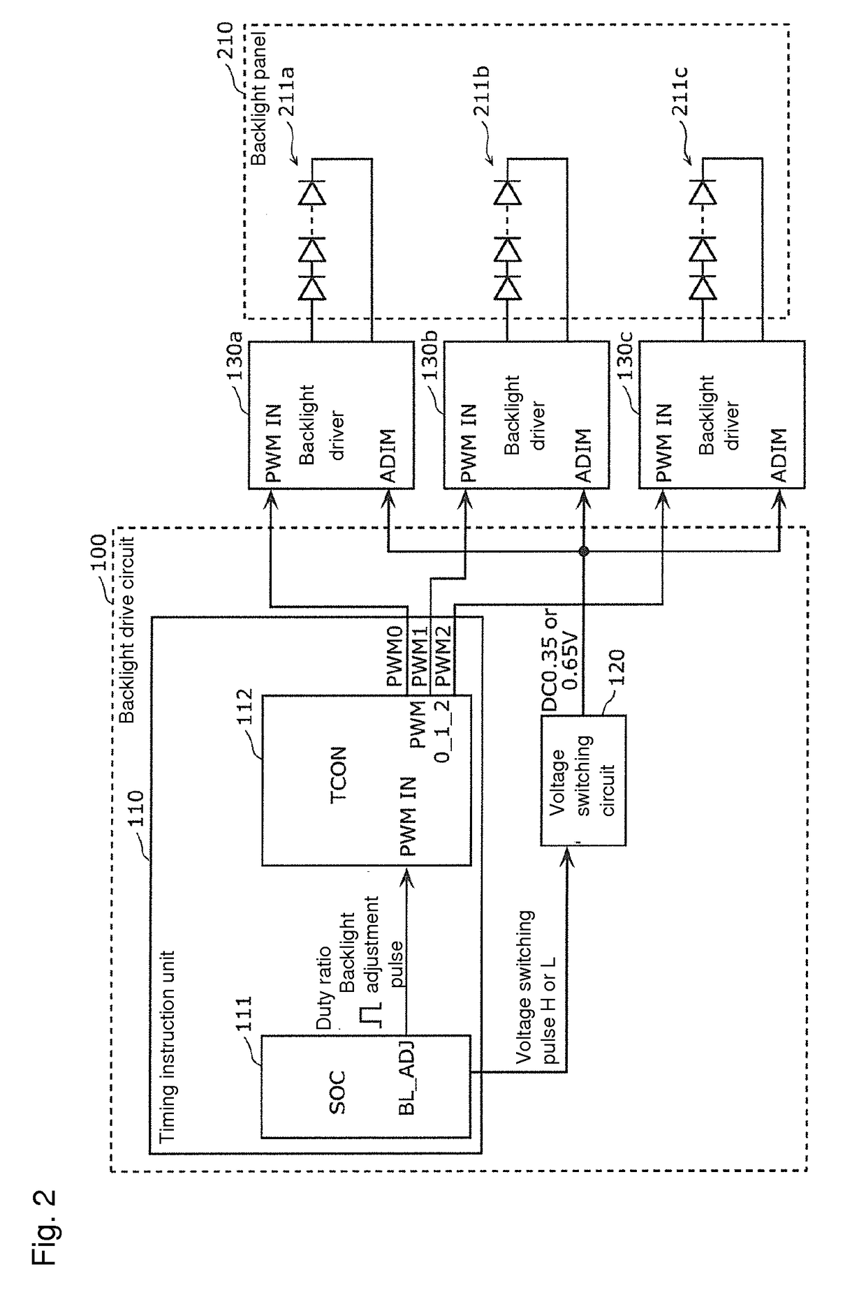
[0170]In the backlight drive circuit 100 according to Preferred Embodiment 1, the SOC 111 and the TCON 112 were preferably used to generate pulse signals PWM0 to PWM2 that correspond to the respective backlight drivers 130a to 130c, but an SOC may be used to build the pulse signals PWM0 to PWM2 without using the TCON 112.

[0171]FIG. 12 is a block diagram showing the detailed constitution of the backlight drive circuit 300 according to a modified example of Preferred Embodiment 1.

[0172]The backlight drive circuit 300 shown in this figure is nearly the same as the backlight drive circuit 100 according to Preferred Embodiment 1, but the difference is that instead of the timing instruction unit 110, a timing instruction unit 310 composed of an SOC 311 is provided.

[0173]The SOC 311 has the functions of the SO...

embodiment 2

Modified Example of Preferred Embodiment 2

[0226]Next, the backlight drive circuit according to a modified example of Preferred Embodiment 2 of the present invention will be described.

[0227]In the backlight drive circuit 400 according to Preferred Embodiment 2, the SOC 411 and the TCON 112 were preferably used to generate pulse signals PWM0 to PWM2 that correspond to the respective backlight drivers 130a to 130c, but an SOC may be used to build the pulse signals PWM0 to PWM2 without using the TCON 112.

[0228]FIG. 20 is a block diagram showing the detailed constitution of the backlight drive circuit 500 according to a modified example of Preferred Embodiment 2.

[0229]The backlight drive circuit 500 shown in this figure is nearly the same as the backlight drive circuit 400 according to Preferred Embodiment 2, but the difference is that instead of the timing instruction unit 410, a timing instruction unit 510 composed of an SOC 511 is provided.

[0230]The SOC 511 has the functions of the SO...


PUM


Abstract

A backlight drive circuit supplies drive current to a plurality of backlights, each of the backlights is extinguished before a signal voltage is written to a liquid crystal pixel group of a line corresponding to the backlight, each drive current in the lit period of each of the backlights is a first current when the adjustment value is a first adjustment value and a second current whose current value is higher than the first current when the adjustment value is a second adjustment value that is lower than the first adjustment value, and the lighting duty ratio to obtain a given luminance using the second current is smaller than the lighting duty ratio to obtain the luminance using the first current.

Description

BACKGROUND OF THE INVENTION1. Field of the Invention[0001]The present invention relates to a backlight drive circuit connected to a liquid crystal panel including groups of liquid crystal pixels disposed in a matrix and a plurality of backlights respectively provided so as to correspond to the plurality of lines of the liquid crystal pixel groups.2. Description of the Related Art[0002]Liquid crystal display devices such as liquid crystal televisions have been getting bigger. However, the problem is that as they grow larger, blurring of images when moving pictures are displayed (hereinafter may also be referred to as “motion blur”) becomes more conspicuous.[0003]Backlight scanning is a known method in liquid crystal display devices to suppress this motion blur. Backlight scanning refers to lighting and extinguishing a plurality of backlights installed for groups of liquid crystal pixels in a display panel in sequence in the line direction.[0004]Such backlight scanning methods include...

Claims


Application Information

Patent Timeline
Patent Type & Authority Patents(United States)
IPC IPC(8): G09G3/36G09G3/34H04N1/00H04N21/488
CPCG09G3/342H04N1/00458H04N21/4886G09G2320/0261G09G2310/0237G09G2320/0247G09G2310/024
Inventor KITA, TATSUYAISHIBASHI, KAZUHIRO
Owner FUNAI ELECTRIC CO LTD
Why Eureka
Try Eureka