
Liquid crystal display and scanning back light driving method thereof

a technology of scanning backlight and liquid crystal display, which is applied in the direction of electric digital data processing, instruments, computing, etc., can solve the problems of screen darkening, scanning backlight driving technology, etc., and achieve the effect of reducing motion blur phenomenon and minimizing the reduction in brightness or luminance of lcd devices

Active Publication Date: 2011-04-14
LG DISPLAY CO LTD
View PDF27 Cites 22 Cited by
  • Summary
  • Abstract
  • Description
  • Claims
  • Application Information

AI Technical Summary

Benefits of technology

[0009]An advantage of the present invention is to provide an LCD device and method of driving a scanning backlight thereof that is capable of reducing a motion blur phenomenon with minimized reduction in the brightness or luminance of the LCD device caused by the scanning backlight driving.

Problems solved by technology

The scanning backlight driving technology is, however, disadvantageous in that the screen becomes darker because the light sources of the backlight are turned off for a certain period of time during every frame interval.

Method used


Image

  • Liquid crystal display and scanning back light driving method thereof
  • Liquid crystal display and scanning back light driving method thereof
  • Liquid crystal display and scanning back light driving method thereof

Examples


Embodiment Construction

[0022]Reference will now be made in detail to an embodiment of the present invention, example of which is illustrated in the accompanying drawings. The same reference numbers may be used throughout the drawings to refer to the same or like parts.

[0023]An embodiment of the present invention is described below with reference to FIGS. 1 to 7.

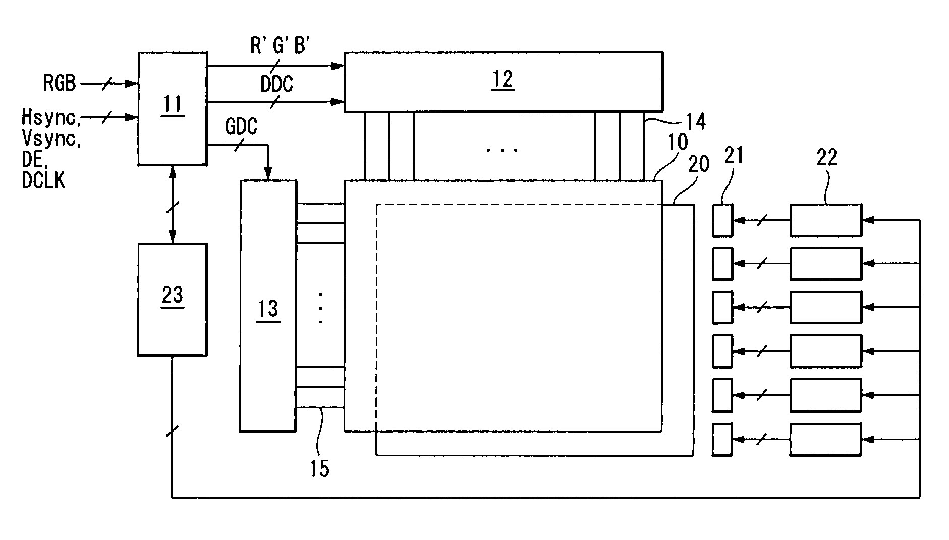
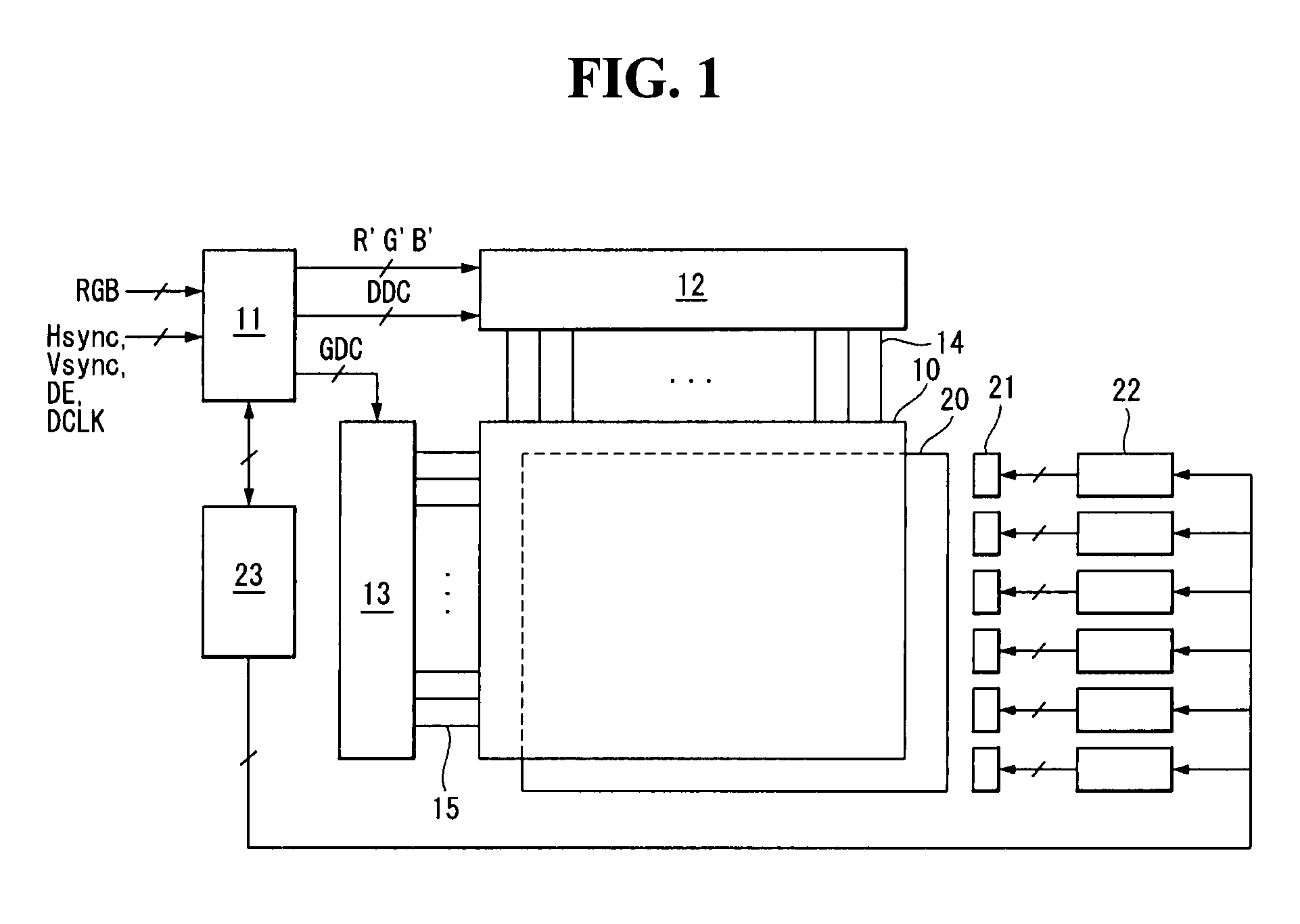
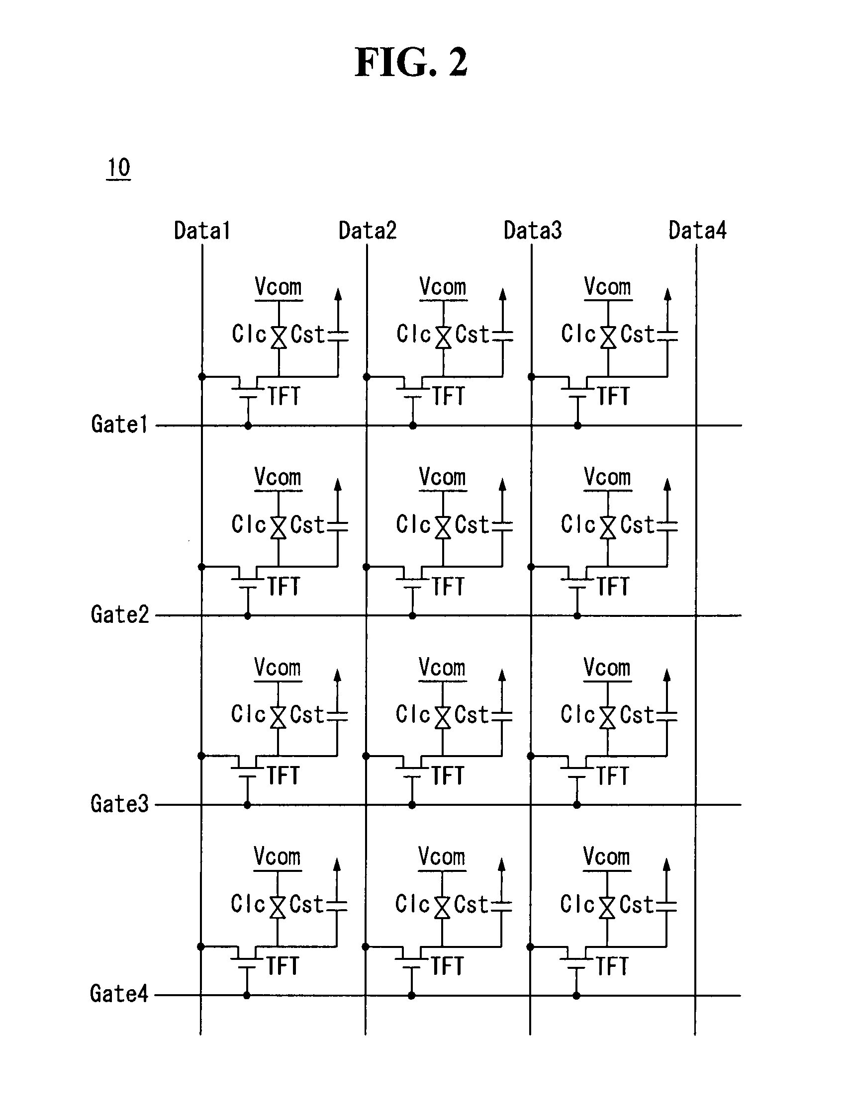
[0024]Referring to FIGS. 1 and 2, a liquid crystal display (LCD) device includes a LCD panel 10, a source driver 12 for driving data lines14 of the LCD panel 10, a gate driver 13 for driving gate lines 15 of the LCD panel 10, a timing controller 11 for controlling the source driver 12 and the gate driver 13, a backlight for providing light to the LCD panel 10, a scanning backlight controller 23 for controlling sequential driving of light sources 21 of the backlight, and light source drivers 22.

[0025]The LCD panel 10 has a liquid crystal layer between two sheets of glass substrates. The data lines 14 and the gate lines 15 cross each other on a lower...


PUM


Abstract

A liquid crystal display (LCD) device and method of the driving the same is disclosed. According to an embodiment of the present invention, an LCD device includes a liquid crystal display panel; a plurality of backlight sources configured to provide light to the liquid crystal display panel; a scanning backlight controller configured to generate a pulse width modulation (PWM) signal for controlling a turn-on time and a turn-off time of the light sources and a current control signal for controlling a driving current of the backlight light sources; and a plurality of light source drivers configured to turn on and off the backlight sources in response to the PWM signal and control the driving current of the backlight sources in response to the current control signal.

Description

[0001]This application claims the benefit of Korean Patent Application No. 10-2009-0095813 filed on Oct. 8, 2009, which is hereby incorporated by reference for all purposes as if fully set forth herein.BACKGROUND[0002]1. Field of the Invention[0003]The present invention relates to a liquid crystal display (LCD) device, and more particularly, to an LCD device and method of driving a scanning backlight thereof.[0004]2. Discussion of the Related Art[0005]Liquid crystal display (LCD) devices are now commonly used in a wide variety of applications because of their characteristics, such as lightweight, thinness, and low power consumption. LCD devices are being used for office automation devices, audio / video devices, indoor / outdoor advertising display devices, and portable computers such as notebook computers. Typical transmission-type LCD devices display images by modulating light incident from a backlight by controlling an electric field applied to a liquid crystal layer.[0006]A viewer m...

Claims


Application Information

Patent Timeline
Patent Type & Authority Applications(United States)
IPC IPC(8): G09G5/10G06F3/038
CPCG09G3/342G09G2320/064G09G2310/024G09G2310/0237G02F1/133G09G3/20G09G3/36
Inventor KIM, JONGHOONSEO, BOGUNMIN, BYUNGSAMJEON, HYUNWOOHEO, JONGGU
Owner LG DISPLAY CO LTD
Learn More