Image reading apparatus equipped with original-size-detection function and image forming apparatus equipped with image reading apparatus

a reading apparatus and original-size detection technology, applied in the direction of electrical apparatus, pictoral communication, etc., can solve the problems of high-speed pwm lighting control, user's glare, electric current, etc., and achieve the effect of reducing glare that a user feels and sufficient accuracy

Inactive Publication Date: 2018-10-09
CANON KK
View PDF20 Cites 0 Cited by
  • Summary
  • Abstract
  • Description
  • Claims
  • Application Information

AI Technical Summary

Benefits of technology

[0009]The present invention provides an image reading apparatus and an image forming apparatus that are capable of reducing glare that a user feels while PWM-controlling an LED as a light source and of detecting an original size in a principal scanning direction with sufficient accuracy.
[0014]According to the present invention, when the original size in the principal scanning direction is detected, the period of the line periodic signal is made longer than that at the time of reading of an original image, and the light-source lighting control signal of which the duty ratio is made smaller than that at the time of reading of the original image is supplied so as to be constant for every period of the line periodic signal. Moreover, the constant electric current is sent by supplying the light-source lighting control signal of which the duty ratio is made smaller than that at the time of reading of an original image, and the image data required for detecting the original size in the principal scanning direction is obtained when the line periodic signal at the time of lighting the light source is recognized. This enables to detect the original size in the principal scanning direction with the sufficient accuracy while reducing the glare that a user feels.

Problems solved by technology

However, if the light source lights and an original size is read before the pressure plate is fully closed, irradiating light goes into a user's eye and there is a problem that the user feels glare.
However, when large electric current that is 1 ampere or more is applied to the LED as a light source in the image reading apparatus disclosed in the above-mentioned publication, the rise of the electric current at a time of lighting and the fall of the electric current at a time of lights-out need time, which makes a high-speed PWM lighting control be difficult.
Since the rise time and fall time of the LED current become long, a high-speed PWM lighting control becomes more difficult.
As a result, since the LED current that flows within the period of the line periodic signal varies, the LED current amount differs for every line period signal, an accurate read original image is not obtained, which degrades accuracy in detection of the original size in the principal scanning direction.

Method used


Image

  • Image reading apparatus equipped with original-size-detection function and image forming apparatus equipped with image reading apparatus
  • Image reading apparatus equipped with original-size-detection function and image forming apparatus equipped with image reading apparatus
  • Image reading apparatus equipped with original-size-detection function and image forming apparatus equipped with image reading apparatus

Examples


first embodiment

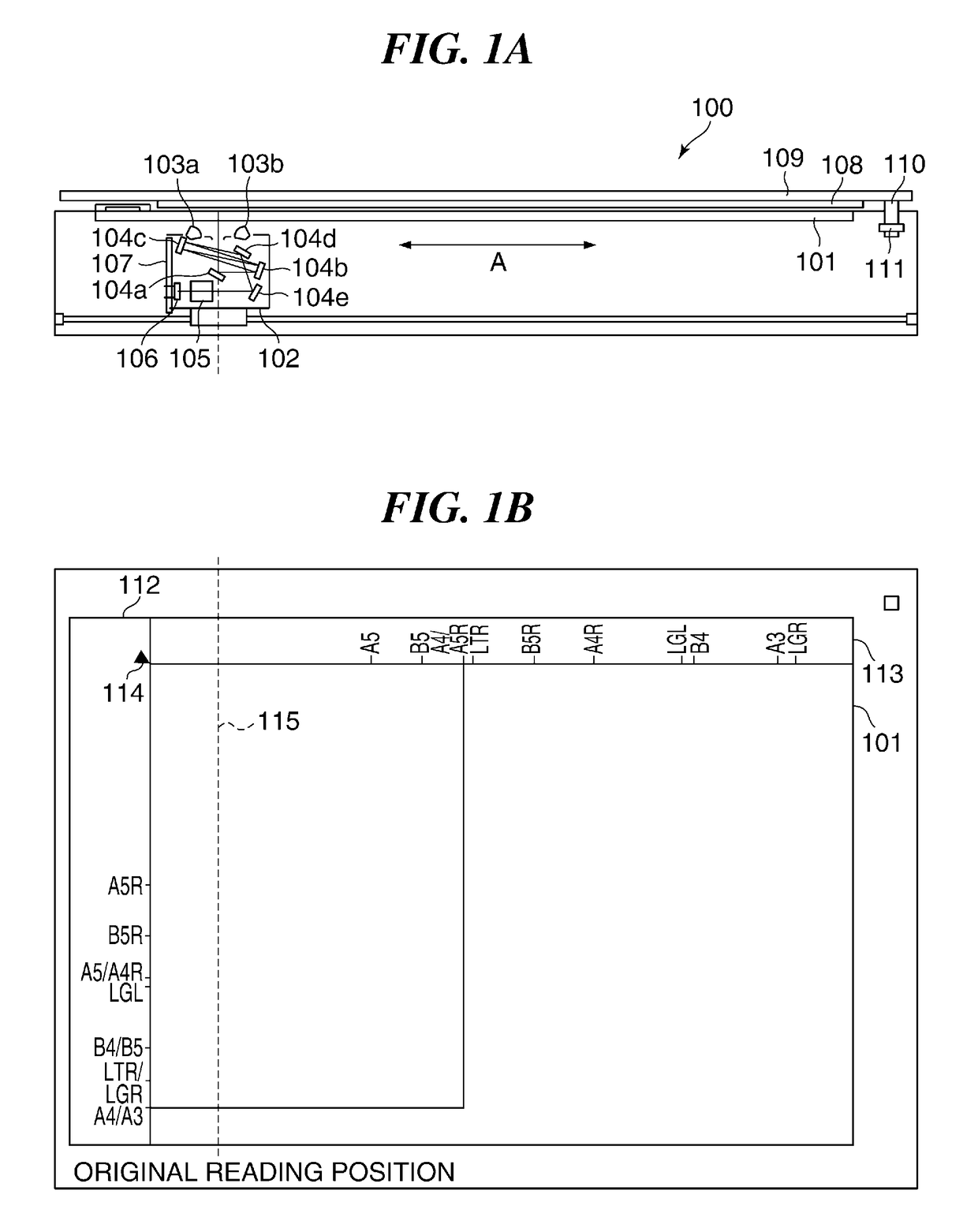
[0025]FIG. 1A is a longitudinal sectional view schematically showing a configuration of an image reading apparatus according to the present invention, and FIG. 1B is a plan view showing a platen of the image reading apparatus shown in FIG. 1A. The image reading apparatus 100 may constitute a part of an image forming apparatus that prints an image read with the image reading apparatus 100 concerned.

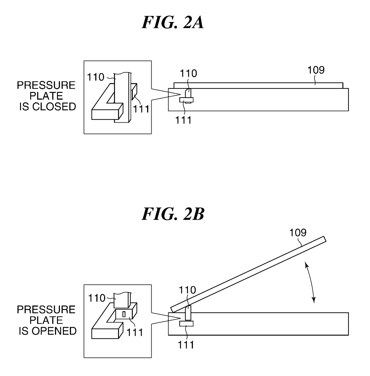
[0026]As shown in FIG. 1A, the image reading apparatus 100 is provided with a platen glass 101 as a platen on which an original is placed, a pressure plate 109 that opens and closes the surface of the platen glass 101, an original pressing plate 108 fixed to the back of the pressure plate 109, and an optical box 102.

[0027]The optical box 102 is arranged in a lower space of the platen glass 101, and is configured to be movable along an arrow A in FIG. 1A. Elements of a reduction optical system are arranged in the optical box 102. That is, lighting units 103a and 103b that irradiate an origi...

second embodiment

[0079]FIG. 6 is a block diagram schematically showing a control system of the image reading apparatus according to the The same reference numeral as the reference numeral used in FIG. 3 is attached to a block in FIG. 6 that has the same function as a block in FIG. 3, and a detailed description about the block concerned is omitted.

[0080]As shown in FIG. 6, the image reading apparatus according to the second embodiment differs from the image reading apparatus according to the first embodiment at a point that the image-processing IC 305 is provided with a PWM determination circuit 601. A timing signal generating circuit (TG) 602 outputs the line sensor control signal including the line periodic signal to the line sensor 106 and outputs the PWM signal to the LED lighting circuit 304 in the same manner as the timing signal generating circuit 302 in FIG. 3. The PWM determination circuit 601 is connected with an output line from the timing signal generating circuit 602 to the line sensor ...


PUM


Abstract

An image reading apparatus is capable of reducing glare that a user feels while PWM-controlling an LED and of detecting an original size in a principal scanning direction with sufficient accuracy. A line sensor receives light emitted from a light source and reflected by an original. When a pressure plate that presses an original to a platen is closed, a control unit controls to supply a line periodic signal of which a period is longer than that for reading an original image to the line sensor, and to supply a lighting control signal of which a duty ratio is smaller than that for reading the original image to the light source in synchronization with the line periodic signal to light the light source and to read an image, and controls to detect length of the original in the principal scanning direction using the image signals from the line sensor.

Description

BACKGROUND OF THE INVENTIONField of the Invention[0001]The present invention relates to an image reading apparatus equipped with an original-size-detection function using a line sensor that reads an original, and an image forming apparatus equipped with the image reading apparatus.Description of the Related Art[0002]There are two methods for detecting a size of an original placed on a platen glass of an image reading apparatus in a principal scanning direction. One uses a dedicated sensor, and the other uses a line sensor that reads an original. A size of an original in the principal scanning direction is detected with using the line sensor at a timing that a user closes a platen cover or a pressure plate provided in a lower side of an automatic document feeder (ADF), for example.[0003]The pressure plate closely fits an original to the platen glass. When it is detected that the user closes the pressure plate, a light source lights and reflected light is read, and brightness read in ...

Claims


Application Information

Patent Timeline
Patent Type & Authority Patents(United States)
IPC IPC(8): H04N1/04H04N1/00H04N1/028
CPCH04N1/00713H04N1/00037H04N1/00737H04N1/00798H04N1/02845H04N1/00774H04N2201/0081
Inventor TOGASHI, KAZUNORI
Owner CANON KK
Why Eureka
Try Eureka