Transmission device and control method for continuously variable transmission

a transmission device and control method technology, applied in the direction of friction gearings, gearing elements, gearings, etc., can solve the problem of inhibiting acceleration performance from being degraded, and achieve the effect of inhibiting acceleration performan

Inactive Publication Date: 2011-05-03
AISIN AW CO LTD
View PDF20 Cites 0 Cited by
  • Summary
  • Abstract
  • Description
  • Claims
  • Application Information

AI Technical Summary

Benefits of technology

[0007]An object of a transmission device and a control method for a continuously variable transmission according to the present invention is to inhibit acceleration performance from being degraded when the vehicle starts moving from a low-speed state.
[0011]In the transmission device according to an aspect of the present invention, the control unit may control the fluid supplying and discharging unit such that, while the vehicle is running in the low-speed state, the pressure of the working fluid in the working fluid chamber is reduced by discharging the working fluid from the working fluid chamber. The reason why the pressure of the working fluid in the working fluid chamber is reduced while the vehicle is running is that it is easy to shift down the continuously variable transmission, because the continuously variable transmission is also operating while the vehicle is running.
[0012]In the transmission device according to an aspect of the present invention, the fluid supplying and discharging unit may include a discharging solenoid valve that functions in such a manner that the higher a duty ratio of an electric current applied thereto is, the more the discharging solenoid valve facilitates the discharging of the working fluid from the working fluid chamber. The control unit may control the fluid supplying and discharging unit such that, while the vehicle is in the low-speed state, the electric current is applied to the discharging solenoid valve in such a manner that the larger a torque input to the continuously variable transmission is, the smaller the duty ratio is. The reason is that, if the torque that is input to the continuously variable transmission is large, the torque that is output as a result of shifting is also large, and it is therefore necessary to keep the pressure of the working fluid in the working fluid chamber, which is necessary to transfer torque, at a certain level. Thus, it is possible to output the input torque after effectively shifting the torque.
[0013]Further, in the transmission device according to an aspect of the present invention, the fluid supplying and discharging unit may include a discharging solenoid valve that functions in such a manner that the higher a duty ratio of an electric current applied thereto is, the more the discharging solenoid valve facilitates the discharging of the working fluid from the working fluid chamber. The control unit may control the fluid supplying and discharging unit such that, while the vehicle is in the low-speed state, the electric current is applied to the discharging solenoid valve in such a manner that the higher a temperature of the working fluid is, the smaller the duty ratio is. Generally, when the temperature of a working fluid becomes high, the viscosity of the working fluid becomes lower. Therefore, by applying the electric current to the discharging solenoid valve in such a manner that the higher the temperature of the working fluid is, the smaller the duty ratio is, it is possible to ensure that the pressure in the working fluid chamber is not reduced too much. Thus, it is possible to regulate the pressure in the working fluid chamber more properly.
[0014]Further, in the transmission device according to an aspect of the present invention, the control unit may control the fluid supplying and discharging unit such that, in a case where a gear ratio of the continuously variable transmission is determined to be a maximum reduction ratio when the vehicle has come into the low-speed state, the working fluid is discharged from the working fluid chamber regardless of the pressure of the working fluid in the working fluid chamber. Thus, it is possible to maintain the continuously variable transmission at the maximum reduction ratio.

Problems solved by technology

As a result, it is possible to inhibit acceleration performance from being degraded when the vehicle starts moving from the low-speed state.

Method used


Image

  • Transmission device and control method for continuously variable transmission
  • Transmission device and control method for continuously variable transmission
  • Transmission device and control method for continuously variable transmission

Examples


Embodiment Construction

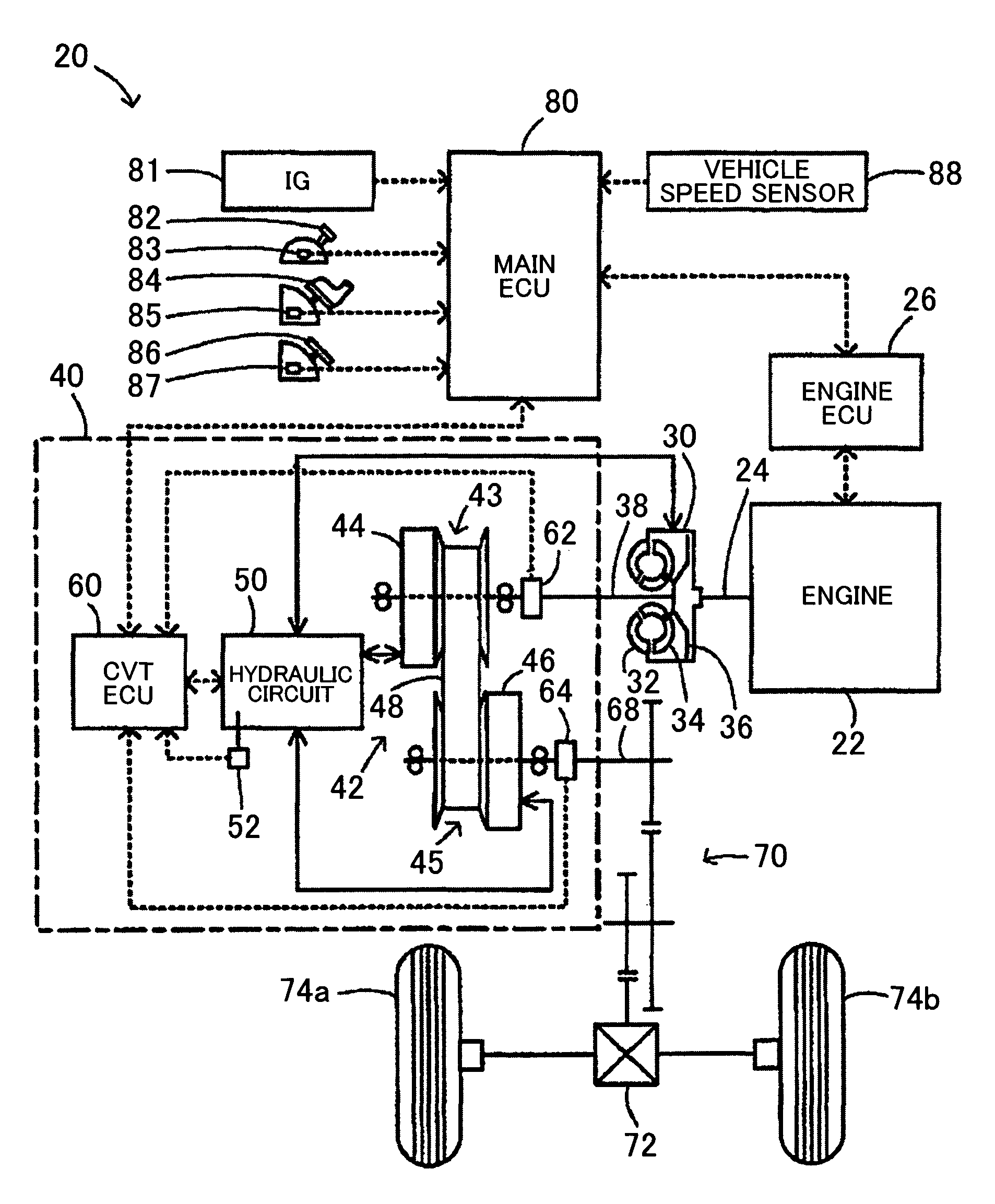
[0024]A preferred embodiment of the present invention will be explained through exemplary embodiments. FIG. 1 is a configuration diagram that schematically shows a configuration of an automobile 20 in which a transmission device 40 according to an embodiment of the present invention is installed. The automobile 20 according to the present embodiment includes an engine 22, a torque converter 30, a transmission device 40, and a main electronic control unit (hereinafter, simply referred to as the “main ECU”) 80. The torque converter 30 includes a lock-up mechanism and is attached, via a damper (not shown in the drawing), to a crankshaft 24, which is an output shaft of the engine 22. The transmission device 40 is connected to an input shaft 38, which is an output shaft of the torque converter 30, and to an output shaft 68, which is connected to drive wheels 74a and 74b via a differential gear 72 and a gear mechanism 70, and that, in principle, outputs the power to the output shaft 68 af...


PUM


Abstract

In the case where a belt return of a continuously variable transmission is not determined when the vehicle speed has become equal to or lower than a threshold value, control that causes a hydraulic actuator to have an intermediate pressure by setting a duty of a duty solenoid based on an input torque and an oil temperature and closing control are repeatedly performed, in accordance with the running and the stopping of the vehicle. As a result, it is possible to inhibit the continuously variable transmission from being shifted up due to a gradual increase in the hydraulic pressure in the hydraulic actuator caused by a line pressure seeping to the hydraulic actuator side through a small clearance in a spool of a flow rate control valve in a hydraulic circuit, and it is also possible to allow the continuously variable transmission to be shifted down.

Description

CROSS REFERENCE TO RELATED APPLICATION[0001]The disclosure of Japanese Patent Application No. 2007-158890 filed on Jun. 15, 2007 including the specification, drawings and abstract is incorporated herein by reference in its entirety.BACKGROUND OF THE INVENTION[0002]1. Field of the Invention[0003]The present invention relates to a transmission device and a control method for a continuously variable transmission. More specifically, the present invention relates to a transmission device including a continuously variable transmission that is installed in a vehicle and that is shifted up by supplying a working fluid to a working fluid chamber and that is shifted down by discharging the working fluid from the working fluid chamber. The present invention also relates to a control method for such a continuously variable transmission.[0004]2. Description of the Related Art[0005]As an example of this type of transmission device, a transmission device including a belt type continuously variable...

Claims


Application Information

Patent Timeline
Patent Type & Authority Patents(United States)
IPC IPC(8): F16H61/662
CPCF16H61/66259F16H2061/6611Y10T477/6203Y10T477/6243Y10T477/6242Y10T477/62429
Inventor KURITA, KIYOSHIHAZU, FUMIHIRO
Owner AISIN AW CO LTD
Why Eureka
Try Eureka