Liquid crystal display device

a liquid crystal display and display device technology, applied in non-linear optics, instruments, optics, etc., can solve the problems of reducing the yield of products, difficult to uniformly disperse spacers, and reducing contrast, so as to increase the mechanical strength of spacers, and reduce the number of steps

Inactive Publication Date: 2005-05-03
AU OPTRONICS CORP
View PDF37 Cites 80 Cited by
  • Summary
  • Abstract
  • Description
  • Claims
  • Application Information

AI Technical Summary

Benefits of technology

[0022]Further, according to the present invention, the number of steps can be decreased by using the spacer itself as a transfer.
[0023]Moreover, according to the present invention, the contact with the rubbing cloth when rubbed is reduced, and hence the spacer assumes a configuration with a small width. With this configuration, the mechanical strength of the spacer can be increased, and both the deterioration of the rubbing cloth and the defect in the orientation can be reduced.
[0024]Further, the contrivance is given in terms of the spacer position so as not to exert an influence of the orientation defect caused ...

Problems solved by technology

In the liquid crystal display device using the plastic beads as a spacer, however, orientations of the liquid crystal peripheral to the spacer, which liquid crystal is scattered between the two substrates, are disordered, resulting in such a tendency that the contrast declines due to a leakage of light beams from the spacer peripheral portion.
Moreover, the spacers are hard to disperse uniformly and are arranged with ununiformity during a step of dispersing the spacers on the substrate.
This results in a display defect, which in turn brings about a decreases in yield of the product.
This might cause a display defect attributed to a deterioration in terms of cell gap.
On the other hand, if a spacer density on the entire surface of the substrate is increased as a countermeasure against the deterioration of the cell gap, there arises a problem in which vacuum bubbles are easy to produce in a liquid crystal layer.
On this occasion, a comparatively large stress (frictional resistance) is applied upon the rubbing cloth because of the pillar-shaped spacer taking a square or round shape, with the result that staples of the rubbing cloth are bent or damaged.
If the rubbing cloth containing defective staples is continuously used, this leads to an execution of an ununiform rubbing process, which in t...

Method used


Image

  • Liquid crystal display device
  • Liquid crystal display device
  • Liquid crystal display device

Examples


first embodiment

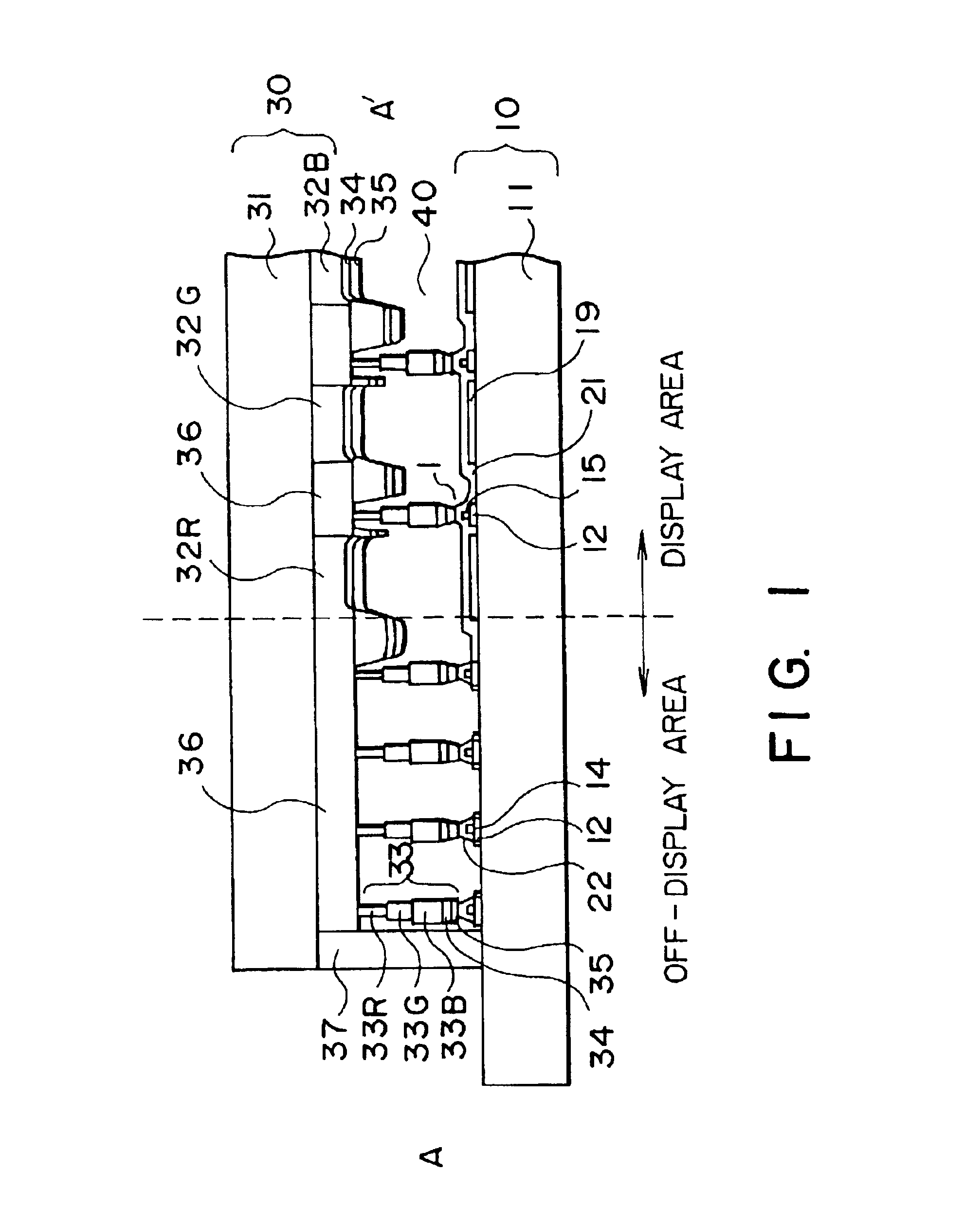
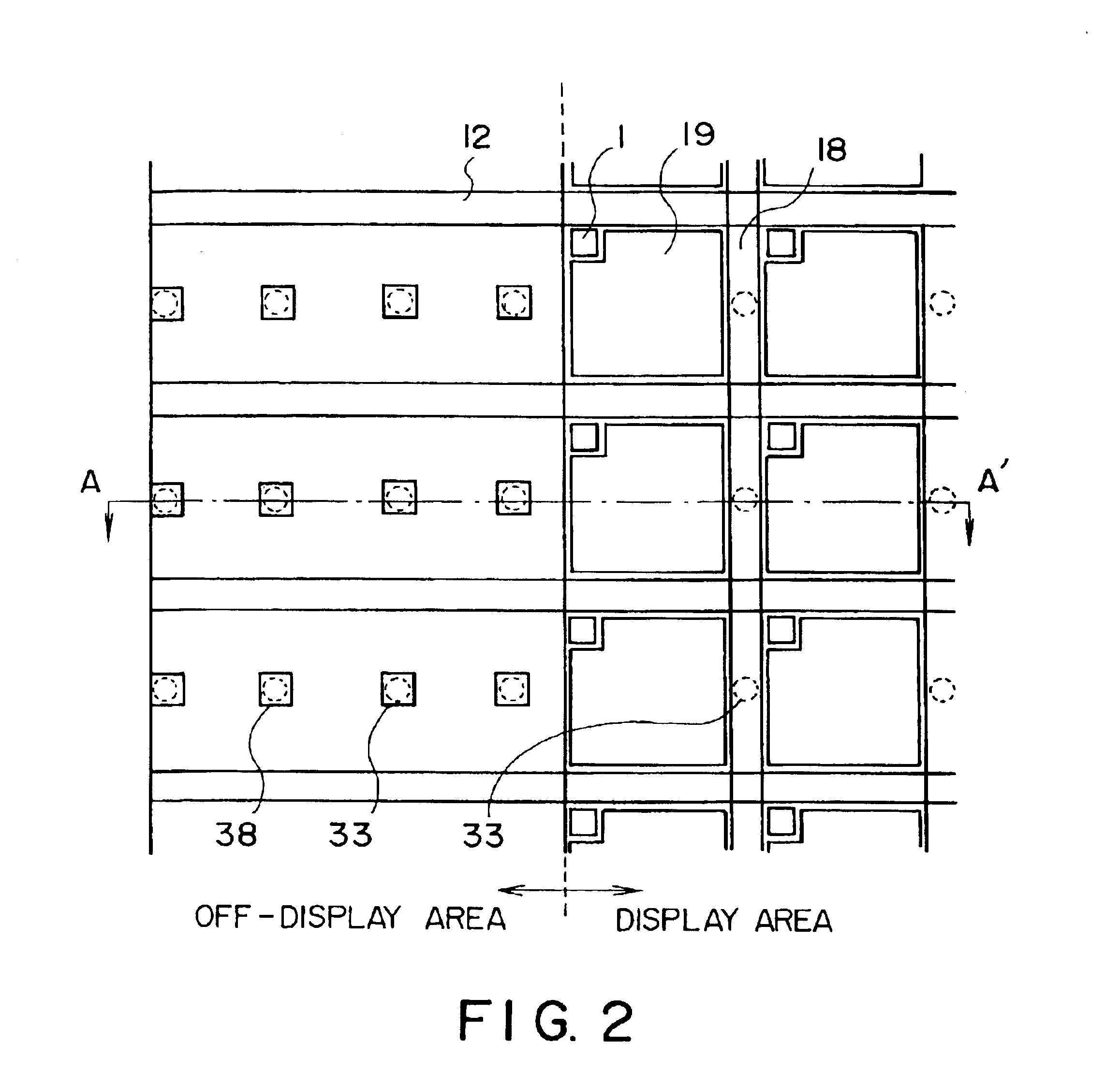
[0064]FIG. 1 is a sectional view illustrating a liquid crystal display device in accordance with the present invention. This sectional view shows a section cut substantially along the line A-A′ in a plan view illustrating an array pattern of FIG. 2. Pixel electrodes 19 corresponding to pixels are arrayed in matrix on a display area. Further, a thin-film transistor (TFT: Thin Film Transistor) 1 serving as a switching element is provided per pixel.

[0065]This liquid display device is structured such that an active matrix substrate 10 defined as a lower substrate and an opposite substrate 30 defined as an upper substrate are disposed in parallel with a liquid crystal 40 interposed therebetween, and the liquid crystal 40 is sealed by a sealing material 37.

[0066]At first, the active matrix substrate 10 is constructed such that a TFT 1 is provided on a glass substrate 11, and the pixel electrode 19 is connected to the TFT 1.

[0067]FIG. 3 is a sectional view of the active matrix substrate. A...

second embodiment

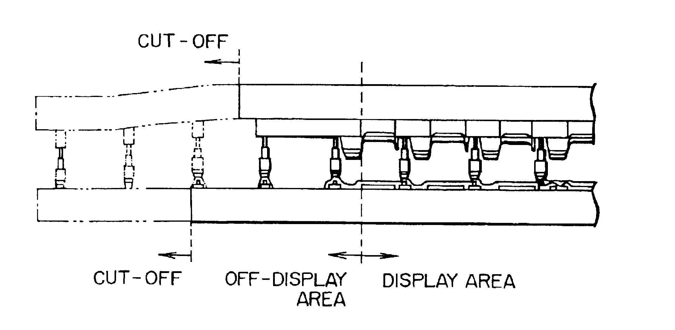
[0090]In accordance with the second embodiment, it is feasible to prevent an occurrence of vacuum bubbles in the vicinity of the display area, which are easy to produce due the enhancement in terms of the density of the number of pillar-shaped spacers 33 and to reduce the cell gap defect.

[0091]A third embodiment will be explained with reference to FIG. 6. In the third embodiment also, the basic structure of the device is the same as that in the first embodiment. However, a volume of the pillar-shaped spacer 33 changed depending on the display area and the off-display area. That is, in the case of the liquid crystal device, the two substrates are disposed substantially in parallel, and an inter-substrate distance is fixed. Therefore, changing the volume of the pillar-shaped spacer has substantially the same meaning as changing the thickness of the pillar-shaped spacer. This can not, however, apply in such a case that the pillar-shaped spacer takes a tapered shape and has the thicknes...

third embodiment

[0092] a diameter of the red color layer 33R partly constituting the pillar-shaped spacer 33 is set to about 10 μm, a diameter of the green color layer 33G is set to about 13 μm, and a diameter of the blue color layer 33B is set to about 16 μm, thus setting the thickness of the pillar-shaped spacer 33 in the display area. The diameter of 33R is about 20 μm, the diameter of 33G is about 26 μm, and the diameter of 33B is about 32 μm, thus setting the thickness thereof in the off-display area.

[0093]A fourth embodiment will be described with reference to FIG. 7. In the fourth embodiment, the off-display area is divided into two subareas, i.e., a subarea (D3) close to the display area and a subarea (D4) far from the display area. The diameter of 33R partly constituting the pillar-shaped spacer 33 is set to about 10 μm, the diameter of 33G is set to about 13 μm, and the diameter of 33B is set to about 16 μm, thus setting the thickness of the pillar-shaped spacer 33 in the display area. Th...


PUM


Abstract

A improved liquid crystal display device including two substrates each having transparent electrode thereon disposed in parallel while keeping a predetermined gap by means of pillar-shaped spacers and a liquid crystal held between said first and second substrates is proposed. In the liquid crystal display device, density or volume of the number of the pillar-shaped spacers provided in the off-display area is higher than those of a density of the number of said pillar-shaped spacers provided in the display area. This change is made continuously or stepwise along areas. The spacers are preferably disposed so that a contact area between the spacer and a rubbing cloth during the rubbing process is minimized, or so that an orientation defective area caused starting from the spacer does not extend into the pixel area, or so that a plurality of spacers are disposed along a flow of liquid crystal from filling port into the gap between the first and second substrate.

Description

[0001]This is a division of U.S. patent application Ser. No. 09 / 388,945 filed Sep. 2, 1999 U.S. Pat. No. 6,445,437, which is a divisional application of U.S. patent application Ser. No. 08 / 708,485, filed Sep. 5, 1996 (now U.S. Pat. No. 5,978,061, issued Nov. 2, 1999, all of which are incorporated herein by reference.BACKGROUND OF THE INVENTION[0002]1. Field of the Invention[0003]The present invention relates generally to a liquid crystal display device and, more particularly, to an improvement pertaining to a pillar-shaped spacer for keeping constant a distance between two substrates for sealing a liquid crystal in the liquid crystal display device.[0004]2. Description of the Background Art[0005]A liquid crystal display device generally employed nowadays is constructed such that two glass substrates having electrodes are set in a face-to-face relationship, peripheries of these two substrates exclusive of a liquid filling port are fixed by a bonding agent, a liquid crystal is interpo...

Claims


Application Information

Patent Timeline
IPC IPC(8): G02F1/13G02F1/1339G02F1/1333
CPCG02F1/13394G02F2001/133388G02F1/133388
Inventor MIYAZAKI, DAISUKEKURAUCHI, SHOICHIHATOH, HITOSHIUENO, AKIKOMIDORIKAWA, TERUYUKIHASEGAWA, MAKOTO
Owner AU OPTRONICS CORP
Why Eureka
Try Eureka