Adhesive stacking for multiple optical films

a technology of optical film and adhesive, applied in the field of optical displays, can solve the problems of increasing the chance of damage to the film when removing the protective lining, the time required to remove the protective lining from individual optical films, and the chance of damage to the film is increased, so as to reduce the number of steps required, reduce the chance of damage to the film, and facilitate the handling of the film

Inactive Publication Date: 2005-03-03
3M INNOVATIVE PROPERTIES CO
View PDF75 Cites 56 Cited by
  • Summary
  • Abstract
  • Description
  • Claims
  • Application Information

AI Technical Summary

Benefits of technology

[0004] In view of the problems listed above, the present invention is directed to a new packaging method in which two or more optical films are held together in a stack together before insertion into the display frame. This makes handling of the films easier, reduces the number of steps required for assembly of the display device, reduces the chance of damaging the films and increases yields.

Problems solved by technology

From a manufacturing perspective, however, several issues can arise from the handling and assembly of several discrete film pieces.
These problems include, inter alia, the excess time required to remove protective liners from individual optical films, along with the increased chance of damaging a film when removing the liner.
In addition, the insertion of multiple individual sheets to the display frame is time consuming and the stacking of individual films provides further opportunity for the films to be damaged.
All of these problems can contribute to diminished overall throughput or to reduced yield, which leads to higher system cost.

Method used


Image

  • Adhesive stacking for multiple optical films
  • Adhesive stacking for multiple optical films
  • Adhesive stacking for multiple optical films

Examples


Embodiment Construction

[0024] The present invention is applicable to displays, such as liquid crystal displays, and is particularly useful for reducing the number of steps required for making such a display.

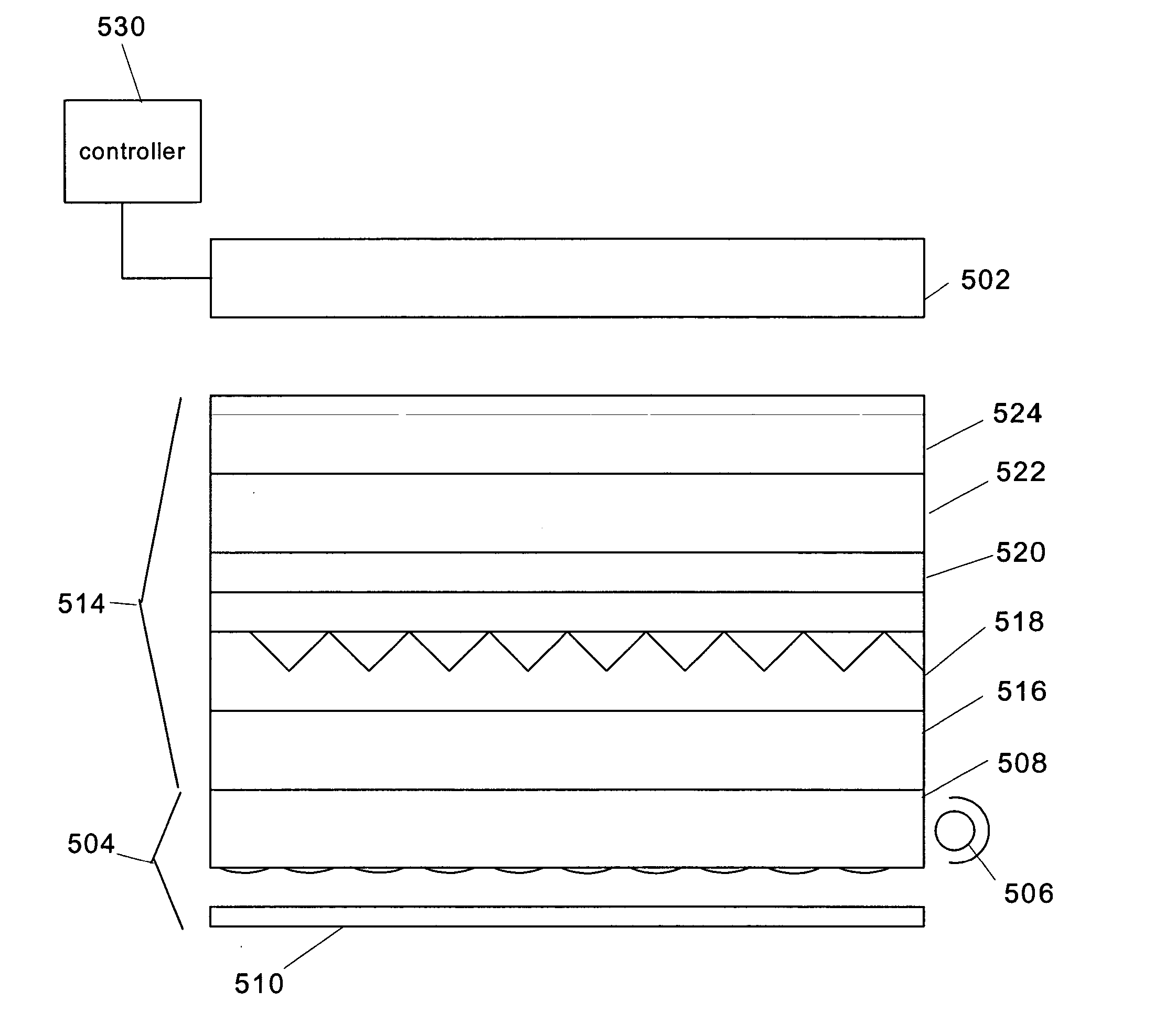
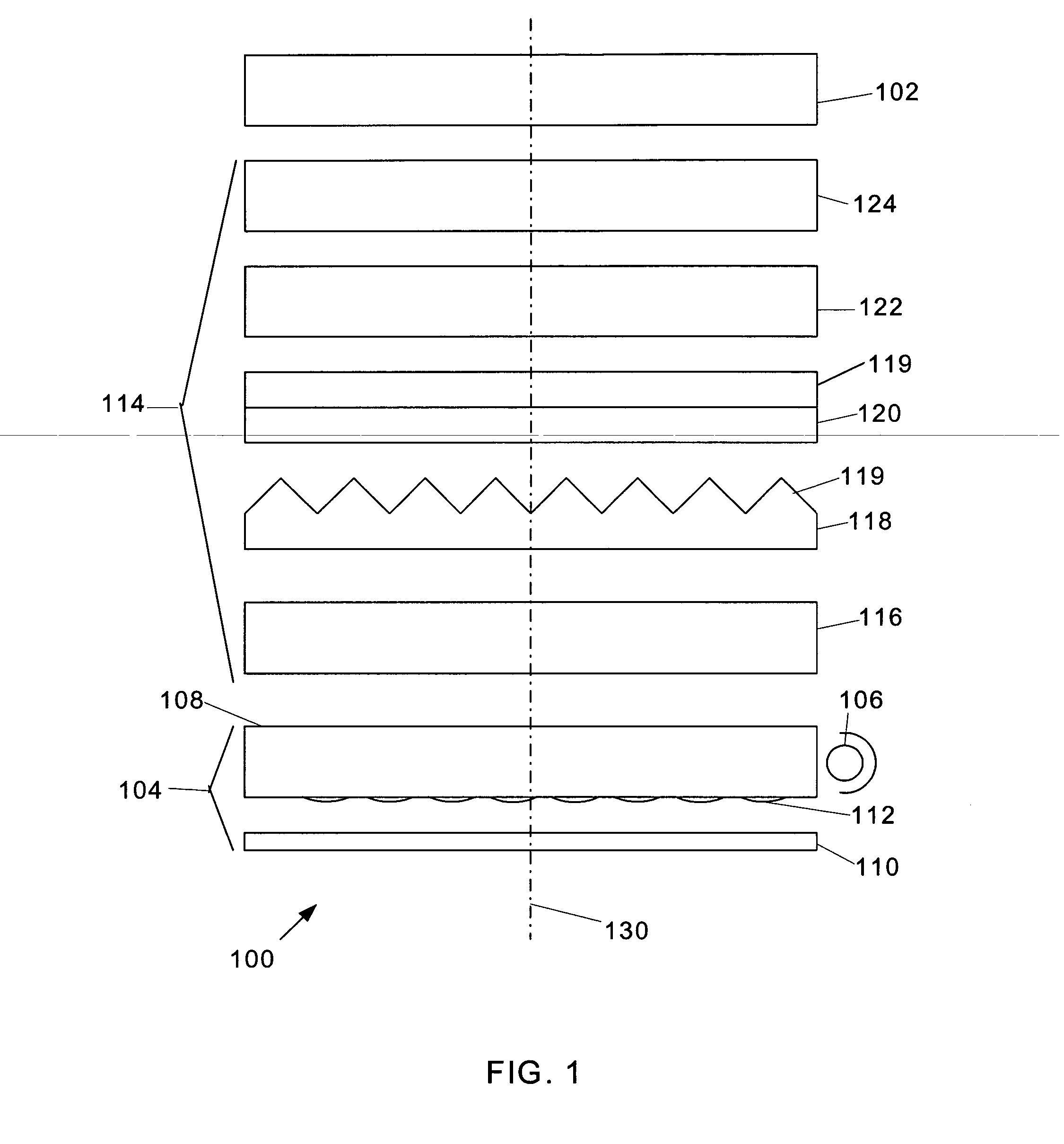
[0025] A display system 100 is schematically shown in FIG. 1. The system includes in electronic display element 102, such as a liquid crystal display (LCD) panel, which is typically sandwiched between two glass layers. Furthermore, the display element 102 may include absorbing polarizers above and below the LCD panel to provide the polarization contrast typically required for producing a polarization-based image.

[0026] A backlight assembly 104 may be used as the primary light source for the display element 102, or may be used for providing light through the display element 102 when there is insufficient ambient light for the user to view the image formed by the display element 102. In one particular embodiment, backlight assembly 104 may include several elements such as a light source 106, a light gu...


PUM

PropertyMeasurementUnit
thicknessaaaaaaaaaa
thicknessaaaaaaaaaa
thicknessaaaaaaaaaa

Abstract

In a new packaging method for light management films in displays, such as liquid crystal displays, a stack of two or more optical films is held together before insertion into the display frame. The stack includes at least two of the films that are adhered together using adhesive positioned outside the viewing area of the films. In some embodiments, the adhesive is provided at one or more tabs provided around the periphery of the film stack.

Description

FIELD OF THE INVENTION [0001] The present invention is directed to optical displays, and more particularly to an approach for packaging light management optical films used in optical displays. BACKGROUND [0002] Optical displays, such as liquid crystal displays (LCDs) are becoming increasingly commonplace, finding use, for example in mobile telephones, hand-held computer devices ranging from personal digital assistants (PDAs) to electronic games, to larger devices such as laptop computers, and LCD monitors and television screens. The incorporation of light management films into optical display devices results in improved display performance. Different types of films, including prismatically structured films, reflective polarizers and diffuser films are useful for improving display parameters such as output luminance, illumination uniformity, viewing angle, and overall system efficiency. Such improved operating characteristics make the device easier to use and may also increase batter...

Claims


Application Information

Patent Timeline
Patent Type & Authority Applications(United States)
IPC IPC(8): G02B7/00G02F1/1335
CPCB32B43/006G02B7/00G02F2202/28G02F2001/133507G02F1/1335G02F1/133507G02B5/20
Inventor FREKING, ANTHONY J.KOTCHICK, KEITH M.
Owner 3M INNOVATIVE PROPERTIES CO
Why Eureka
Try Eureka