Three-dimensional vision sensor

a three-dimensional vision and sensor technology, applied in the field can solve the problems of preventing the efficient creation of three-dimensional models and the output of recognition noise, and achieve the effect of improving the convenience of three-dimensional vision sensors and excellent accuracy

Inactive Publication Date: 2010-09-16
ORMON CORP
View PDF30 Cites 81 Cited by
  • Summary
  • Abstract
  • Description
  • Claims
  • Application Information

AI Technical Summary

Benefits of technology

[0011]Further, if an image of an object existing below a target object is captured along with the target object during recognizing processing, a result of the recognition of this object may be outputted as a noise. Further, in cases where measurement is performed on a model of a target object for creating a three-dimensional model for use in three-dimensional matching processing, similarly, if an image pickup is performed at a state where an object existing below the model falls within the camera, this will involve processing for eliminating noises from the measured three-dimensional coordinates, thereby preventing the creation of the three-dimensional model from being performed efficiently.
[0029]With the aforementioned three-dimensional vision sensor, it is possible to freely define a plane which functions as a reference for height recognition processing according to the surface for actually supporting the recognition-target object and the purpose of the processing, thereby largely improving the convenience of the three-dimensional vision sensor.

Problems solved by technology

Further, there may be cases where recognition-target objects are not supported horizontally, depending on jigs for supporting the recognition-target objects.
Further, if an image of an object existing below a target object is captured along with the target object during recognizing processing, a result of the recognition of this object may be outputted as a noise.
Further, in cases where measurement is performed on a model of a target object for creating a three-dimensional model for use in three-dimensional matching processing, similarly, if an image pickup is performed at a state where an object existing below the model falls within the camera, this will involve processing for eliminating noises from the measured three-dimensional coordinates, thereby preventing the creation of the three-dimensional model from being performed efficiently.
Further, even when an image of an object existing below the model is captured during an image pickup, the result of the measurement on this object is not reflected on the three-dimensional model.

Method used


Image

  • Three-dimensional vision sensor
  • Three-dimensional vision sensor
  • Three-dimensional vision sensor

Examples


first embodiment

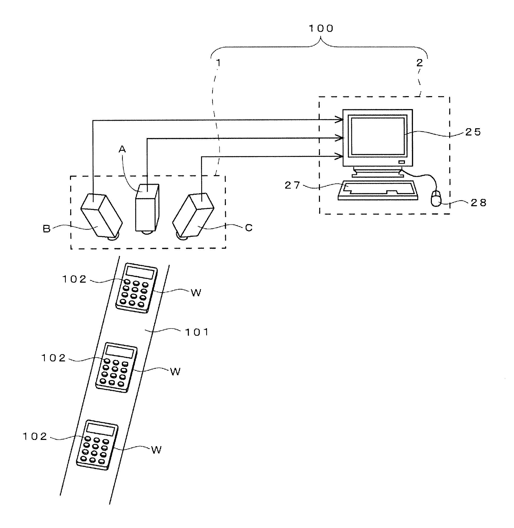
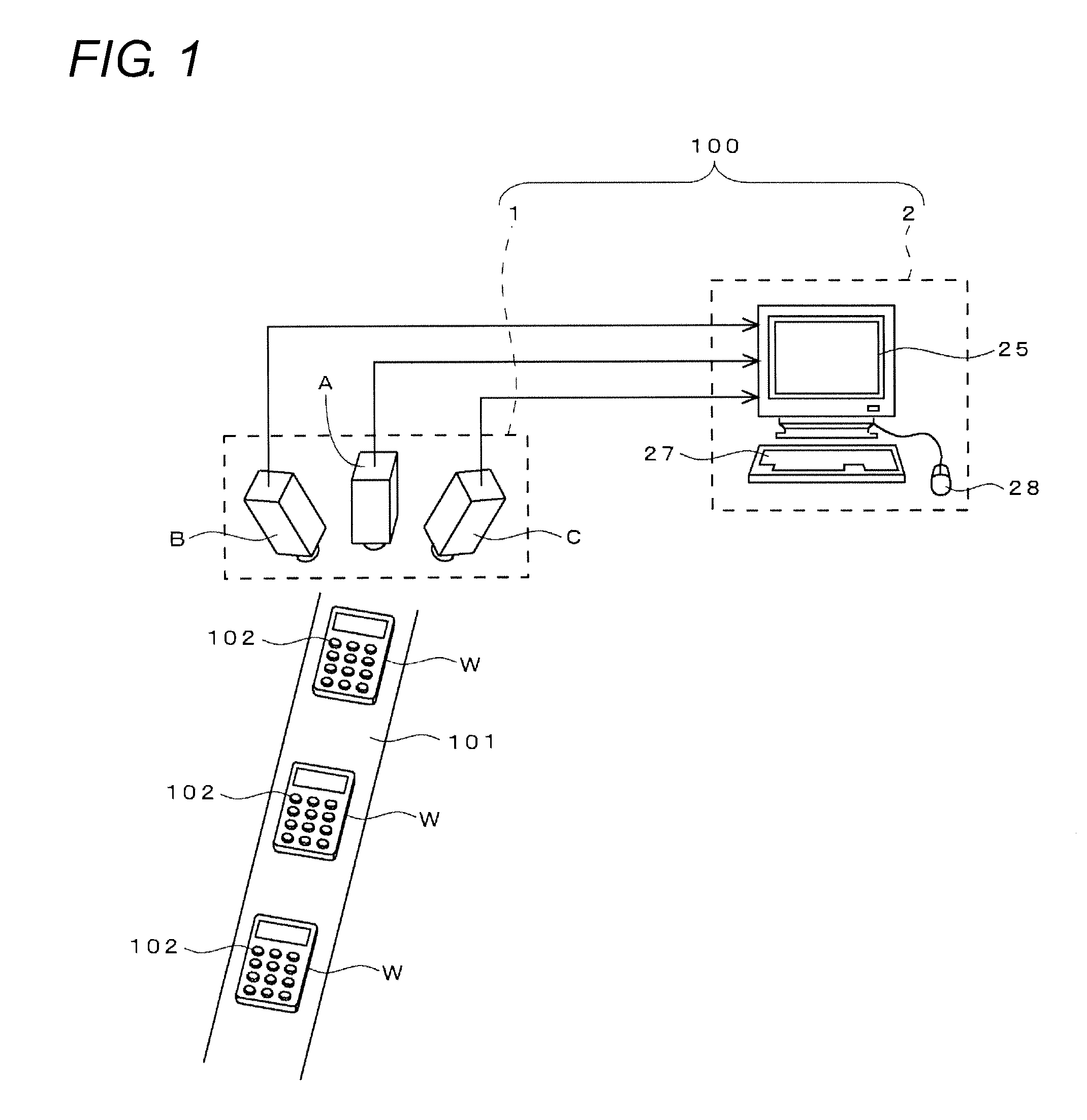
[0045]FIG. 1 illustrates an embodiment of an inspection line which employs a three-dimensional vision sensor.

[0046]This inspection line is for performing, on works W (remote control apparatuses, specifically) having the same shape which have been produced in a factory, inspections as to whether or not heights of push buttons 102 provided on upper surfaces of their cabinets are proper.

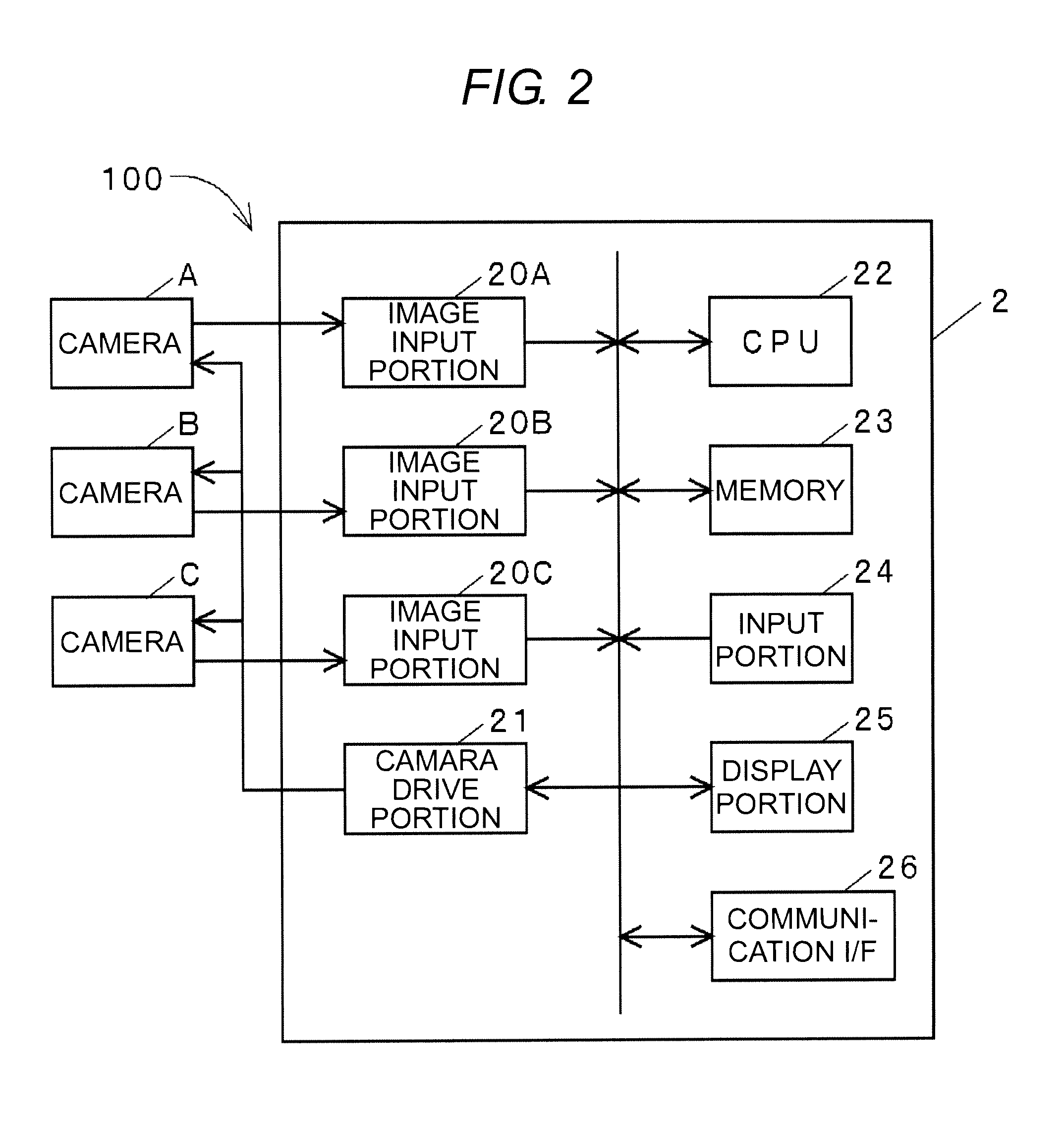
[0047]A three-dimensional vision sensor 100 in the present embodiment is configured by a stereo camera 1 provided above a transfer line 101 for works W, and a recognition processing apparatus 2 provided near the transfer line 101. The stereo camera 1 is configured by three cameras A, B and C which are laterally arranged. The center camera A, among them, is placed at a state where its optical axis is oriented in a vertical direction (that is, when viewed at its front surface), while the left and right cameras B and C are placed such that their optical axes are oblique.

[0048]The recognition processing app...


PUM


Abstract

An object of the present invention is to enable performing height recognition processing by setting a height of an arbitrary plane to zero for convenience of the recognition processing. A parameter for three-dimensional measurement is calculated and registered through calibration and, thereafter, an image pickup with a stereo camera is performed on a plane desired to be recognized as having a height of zero in actual recognition processing. Further, three-dimensional measurement using the registered parameter is performed on characteristic patterns (marks m1, m2 and m3) included in this plane. Three or more three-dimensional coordinates are obtained through this measurement and, then, a calculation equation expressing a plane including these coordinates is derived. Further, based on a positional relationship between a plane defined as having a height of zero through the calibration and the plane expressed by the calculation equation, a transformation parameter (a homogeneous transformation matrix) for displacing points in the former plane into the latter plane is determined, and the registered parameter is changed using the transformation parameter.

Description

BACKGROUND OF THE INVENTION[0001]This application is based on Japanese Patent Application No. 2009-059919 filed with the Japan Patent Office on Mar. 12, 2009, the entire content of which is hereby incorporated by reference.[0002]1. Technical Field[0003]The present invention relates to a three-dimensional vision sensor for recognizing a target object through three-dimensional measurement processing using a stereo camera.[0004]2. Related Art[0005]In order to perform three-dimensional measurement using a stereo camera, it is necessary to determine a perspective transformation matrix P (refer to the following equations (1) and (2)) in a transformation equation indicative of a relationship between a world coordinate system and a coordinate system of each camera constituting the stereo camera.(Equation1)λ[xy1]=P[XYZ1](1)(Equation2)P=[P00P01P02P03P10P11P12P13P20P21P22P23](2)[0006]The respective components P00, P01, . . . P23 in the perspective transformation matrix P reflect internal param...

Claims


Application Information

Patent Timeline
Patent Type & Authority Applications(United States)
IPC IPC(8): G06K9/00
CPCG06T7/002G06T2207/30164G06T2207/10012G06T7/85G06F18/00
Inventor FUJIEDA, SHIROTANENO, ATSUSHIYANO, HIROSHIIKEDA, YASUYUKI
Owner ORMON CORP
Why Eureka
Try Eureka