
A fault monitoring and alarming method and device

A fault monitoring and alarm device technology, applied in digital transmission systems, electrical components, transmission systems, etc., can solve problems such as difficulty in solving faults in a timely manner, economic losses, and difficulty in timely delivery of alarm information from other equipment or components to the receiver. The effect of improving transmission efficiency and equalization of transmission opportunities

Inactive Publication Date: 2017-08-11
BEIJING QIHOO TECH CO LTD +1
View PDF6 Cites 0 Cited by
  • Summary
  • Abstract
  • Description
  • Claims
  • Application Information

AI Technical Summary

Problems solved by technology

However, as the scale of the current computer room system increases, the number of devices that need to be monitored increases correspondingly, and the functions of the monitored devices also increase accordingly. When an emergency occurs, the failure of one server may cause hundreds or even hundreds of messages. Thousands of alarm information, so it is easy to backlog alarm information, making it difficult for the alarm information of other equipment or components to be delivered to the receiver in time, making it difficult to solve the fault in time, reducing the efficiency of fault repair, and even causing large economic losses

Method used


Image

  • A fault monitoring and alarming method and device
  • A fault monitoring and alarming method and device
  • A fault monitoring and alarming method and device

Examples


Embodiment Construction

[0037] In order to make the object, technical solution and advantages of the present invention clearer, the present invention will be further described in detail below in conjunction with specific embodiments and with reference to the accompanying drawings.

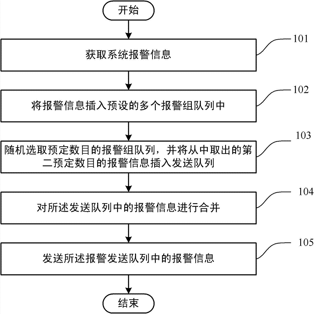
[0038] figure 1 It is a flowchart of a fault monitoring and alarming method proposed by the present invention. Such as figure 1 As shown, the method includes:

[0039] Step 101: Obtain system alarm information;

[0040] Step 102: inserting the alarm information into a plurality of preset alarm group queues;

[0041] Step 103: Randomly select a predetermined number of alarm group queues, and insert a second predetermined number of alarm information extracted therefrom into the sending queue;

[0042] Step 104: Merge the alarm information in the sending queue;

[0043] Step 105: Send the alarm information in the sending queue.

[0044] Each step of the above fault monitoring and alarming method proposed by the present...


PUM


Abstract

The invention discloses a fault monitoring and alarm method, comprising: obtaining system alarm information; inserting the alarm information into a plurality of preset alarm group queues; randomly selecting a predetermined number of alarm group queues, and extracting the alarm information Inserting into the sending queue; merging the alarm information in the sending queue; sending the alarm information in the sending queue. The present invention has equal sending opportunities for each alarm group, improves sending efficiency by merging alarm information, and solves the problem that alarm information is backlogged and cannot be solved in time under emergency conditions.

Description

technical field [0001] The invention relates to the field of equipment fault detection, in particular to a fault monitoring and alarming method and device. Background technique [0002] With the continuous development of information network technology, various network equipment rooms of different sizes, equipment types, and quantities are widely distributed in the regions where branches are located. Due to the lack of an operation and maintenance system that is proportional to the scale system of the operating network, the Changes in the physical operating environment, equipment operating conditions, personnel activities, and firefighting conditions of numerous unattended computer rooms, including possible computer conditions, cannot be discovered and dealt with in a timely manner, and it is difficult to be effectively predicted, prevented and avoid. Therefore, a complete computer room monitoring system is very important for the computer room environment monitoring. [000...

Claims


Application Information

Patent Timeline
Patent Type & Authority Patents(China)
IPC IPC(8): H04L12/24H04L12/26
Inventor 曾文杰
Owner BEIJING QIHOO TECH CO LTD
Learn More