Sintering heat preservation device, sintering machine and sintering method thereof

A thermal insulation device and sintering material technology, which is applied in the field of sintering thermal insulation devices, can solve problems such as uneven air volume, large gas consumption, and wind grabbing, and achieve the effects of reducing the rate of return ore, improving sintering quality, and reducing floor space

Pending Publication Date: 2019-10-18
MAANSHAN IRON & STEEL CO LTD
View PDF10 Cites 6 Cited by
  • Summary
  • Abstract
  • Description
  • Claims
  • Application Information

AI Technical Summary

Problems solved by technology

[0016] Aiming at the problems of the existing heat preservation cover during sintering production, such as air grabbing from the ignition furnace, large gas consumption, rapid cooling of the material surface, or uneven air volume entering the horizontal material surface of the trolley, the present invention provides a sintering heat preservation device, which It can make full use of the heat lost on the surface of the sintering material, form a gradually decreasing trapezoidal temperature field, and supply uniform and sufficient oxygen to the cross-sectional direction of the sintering trolley, improve the uniformity of oxygen supply in the cross-section of the sintering trolley, thereby improving the temperature of the sintering material. Improve the sintering quality of the upper part of the layer and reduce the return rate

Method used


Image

  • Sintering heat preservation device, sintering machine and sintering method thereof
  • Sintering heat preservation device, sintering machine and sintering method thereof
  • Sintering heat preservation device, sintering machine and sintering method thereof

Examples


Embodiment 1

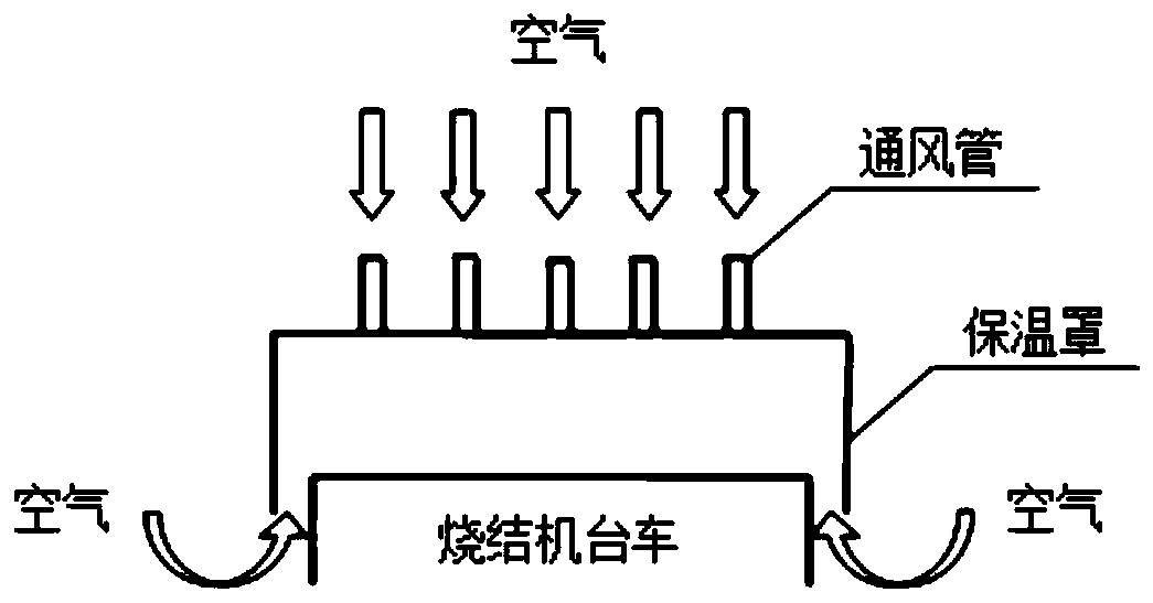
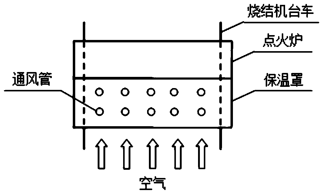
[0054] In sintering production, after the sintering material is ignited, the sintering material needs to be kept warm. In the prior art, a heat preservation furnace or a heat preservation cover is generally installed after the ignition furnace to keep the sintered material surface away from the ignition furnace 2. However, simply taking the form of a heat preservation cover can reduce a large amount of heat loss on the surface of the sintered material, but its air or oxygen supply is relatively insufficient, and under the action of the negative pressure of the exhaust system under the sintering trolley, the sintered material will Grab the wind from the ignition furnace 2 above the surface, which affects the work of the ignition furnace. However, if air is introduced through openings on the insulation cover, or from the rear of the insulation cover or the gaps on both sides, it is easy to cause rapid cooling of the sintered material surface, affect the sintering quality, and inc...

Embodiment 2

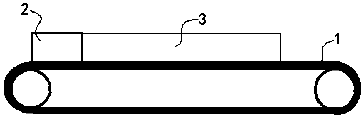
[0064] like image 3 As shown, a sintering machine is mainly used for sintering operations in metallurgical sintering plants, sintering various ore powders into blocks, and partially eliminating harmful impurities in the ore. It includes a sintering trolley 1, an ignition furnace 2 and a heat preservation device. Among them, the sintering trolley 1 is the main operating part of the sintering machine, and the sintering material is ignited, sintered, cooled, etc. on the sintering trolley, and an exhaust system is installed below it, usually using an exhaust fan and other devices. The ignition furnace 2 is installed above the feed end of the sintering trolley 1, and is used to ignite the sintering material. The thermal insulation device adopts a sintering thermal insulation device in Example 1, which can supply sufficient oxygen to the sintered material layer while maintaining thermal insulation, and improve the quality of the upper part of the sintered material layer and the un...

Embodiment 3

[0066] A kind of sintering method of sintering machine, adopts the sintering machine of embodiment 2 to carry out sintering work, comprises the steps:

[0067] 1. Turn on the ignition furnace 2. The ignition temperature is 900-1150°C. After the sintering material is distributed on the sintering trolley, the sintering trolley 1 transports the sintering material through the ignition furnace 2 at a running speed of 1.0-2.5m / min to ignite. The embodiment takes 2m / min. It should be noted that the running speed of the sintering trolley 1 needs to be selected according to the actual working conditions, but generally does not exceed the above range; after that, the sintering material enters the heat preservation cover 3, and the length of the heat preservation cover 3 is based on the actual The production process is set, generally kept within 2-10m, and 6m is taken in this embodiment.

[0068] 2. The lower part of the heat exchanger 31 receives heat radiation from the surface of the s...


PUM


Abstract

The invention discloses a sintering heat preservation device, a sintering machine and a sintering method thereof, and belongs to the field of sintering equipment. The heat preservation device comprises a heat preservation cover with an upper opening and a lower opening, a heat exchanger is arranged in the heat preservation cover, the upper opening of the heat preservation cover is sealed, and theheat exchanger is used for preheating the outer air entering the heat preservation cover during sintering operation; and the heat preservation device can fully utilize the heat dissipated by the sintering material surface to form a gradually-reduced trapezoidal temperature field, and the oxygen supply uniformity of the cross section of a sintering trolley is improved, so that the sintering qualityof the upper part of the sintering material layer is improved, and the ore return rate is reduced. The sintering machine comprises the sintering trolley, a ignition furnace and the heat preservationdevice, the sintering machine can supply sufficient oxygen to the sintering material layer while preserving heat, and the quality of the upper part of the sintering material layer and the uniformity of the sintering cross section are improved. According to the sintering method, the above sintering machine is adopted, through setting a reasonable sintering process, the sintering material surface can be ensured to be slowly and uniformly cooled in an environment with sufficient oxygen, the sintering is uniform, and the sintering quality is improved.

Description

technical field [0001] The invention belongs to the field of sintering equipment, and more specifically relates to a sintering heat preservation device, a sintering machine and a sintering method thereof. Background technique [0002] After sintering and ignition, heat preservation treatment can reduce the heat lost from the surface of the sinter layer, avoid the rapid cooling of the surface sinter, prolong the formation time of the surface sinter binder phase, and at the same time facilitate the reduction of calcium ferrite minerals in the binder phase and strength enhancement. However, the imperfect insulation system will easily lead to undermelting on the surface of the material layer, floating ash on the surface of the sinter, and a large amount of return ore, which will lead to a decrease in sintering productivity, a decrease in the metallurgical properties of the sintering ore, and an increase in sintering energy consumption. [0003] The ignition and heat preservatio...

Claims


Application Information

Patent Timeline
Patent Type & Authority Applications(China)
IPC IPC(8): C22B1/16
CPCC22B1/16
Inventor 武轶李邦平周江虹郑兴荣李小静王军黄世来
Owner MAANSHAN IRON & STEEL CO LTD
Why Eureka
Try Eureka