Cutting debris crushing device, cutting debris crushing blade, and cutting debris crushing data collection method

The technology of a shredding device and a shredding knife is applied in the direction of grain processing, etc., which can solve the problems of difficult implementation of handling or recycling, and achieve the effects of improving the efficiency of shredding treatment, avoiding cost increase, and preventing damage.

Inactive Publication Date: 2014-03-26
AISIN AI CO LTD
View PDF10 Cites 5 Cited by
  • Summary
  • Abstract
  • Description
  • Claims
  • Application Information

AI Technical Summary

Problems solved by technology

[0002] Chips generated during cutting are curled in a long spiral, so it is difficult to carry out transportation or recycling.

Method used


Image

  • Cutting debris crushing device, cutting debris crushing blade, and cutting debris crushing data collection method
  • Cutting debris crushing device, cutting debris crushing blade, and cutting debris crushing data collection method
  • Cutting debris crushing device, cutting debris crushing blade, and cutting debris crushing data collection method

Examples


Embodiment Construction

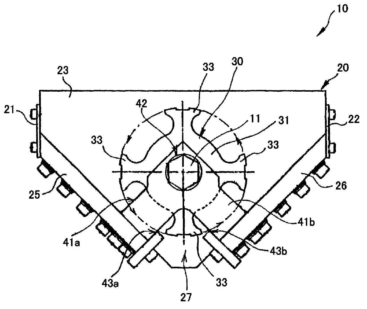
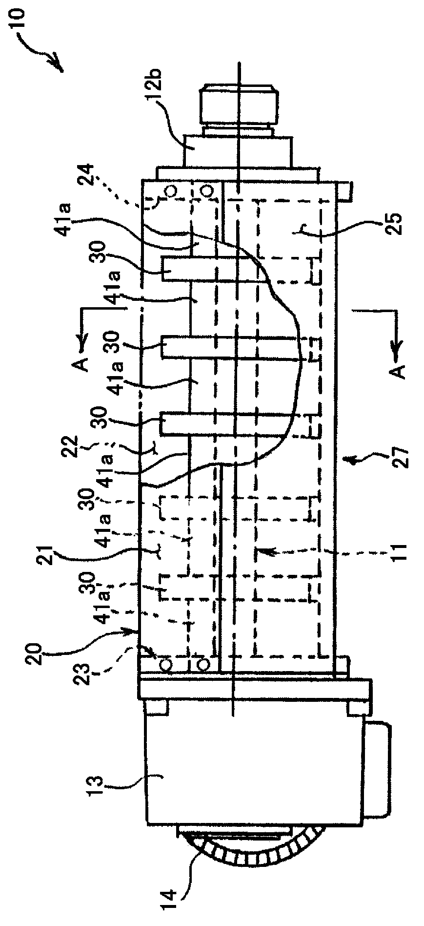
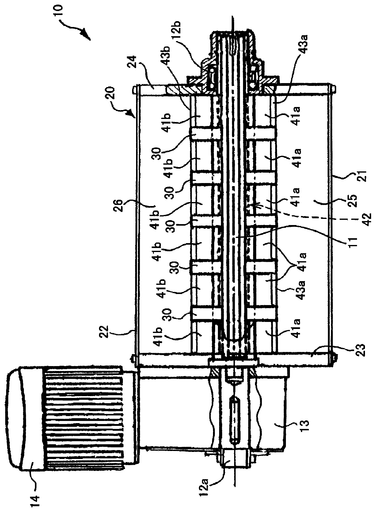
[0053] Hereinafter, the chip shredding device of the present invention will be further described in detail according to the embodiments shown in the drawings. Figure 1 ~ Figure 3 It is a schematic diagram showing a chip crushing device according to an embodiment of the present invention. figure 1 Yes figure 2 The A-A direction of the sectional view. figure 2 is the front view of the chip shredding device, image 3 It is a plan view of the chip shredding device.

[0054] The chip crushing device 10 of the present embodiment rotatably supports a rotary drive shaft 11 by bearing portions 12 a and 12 b in a case 20 opened on the upper surface.

[0055] Housing 20 is made of front side plate 21, rear side plate 22, left side plate 23, right side plate 24, front base plate 25, rear base plate 26, as figure 2 and image 3 As shown, it is formed longer in the left-right direction.

[0056] like figure 1 As shown, the front base plate 25 and the rear base plate 26 are inclin...


PUM


Abstract

The invention provides a cutting debris crushing device which efficiently crushes long cutting debris or tangled cutting debris by making it difficult for cutting scraps to escape from a crushing blade. A cutting debris crushing device is provided with: multiple cutting debris crushing blades having base parts securely attached at an interval to a rotation drive shaft disposed within a casing that opens to the top surface, and at least one rotating blade which extends from the base parts in the outer circumferential direction; multiple first secure blades which come into contact with the side surfaces of the cutting debris crushing blades and which crush cutting debris in cooperation with the blade part on the side surface of the rotating blade of the cutting debris crushing blades and multiple second secure blades for crushing cutting debris in cooperation with the blade part on the outer circumference of the rotating blade of the cutting debris crushing blades. The rotating blade of the cutting debris crushing blades is provided with raking blades having a rake angle relative to the rotation circumferential direction, and straight blades extending in the outer circumferential direction from the rake blades.

Description

technical field [0001] The present invention relates to a chip shredding device, a chip shredding knife, and a method for collecting chip shredding data of the chip shredding device, in particular to the following chip shredding device, chip shredding knife, and the chip shredding device The chip chipping data collection method can efficiently chip long chips or tangled chips by making it difficult for chips to escape from the chopping blade when chipping chips. Background technique [0002] Chips generated during cutting are curled in a long spiral, so it is difficult to transport or recycle them. Therefore, the chips are usually shredded into shorter sizes using a device for shredding the chips. [0003] Conventionally, as shown in, for example, Japanese Patent Document 1 or Patent Document 2, efforts have been made to reliably and efficiently cut chips into fine pieces. [0004] In the cutting chip chipping method disclosed in Japanese Patent Document 1, metal chips are...

Claims


Application Information

Patent Timeline
Patent Type & Authority Applications(China)
IPC IPC(8): B02C18/14B02C18/18
CPCB02C18/14B02C2018/188B02C18/18Y02P70/10
Inventor 佐田速夫
Owner AISIN AI CO LTD
Why Eureka
Try Eureka