
pneumatic tire

A pneumatic tire, tire circumferential technology, applied in tire parts, tire sidewalls, transportation and packaging, etc., can solve the problem of inability to obtain the visual concealment effect of the recess, and achieve the effect of improving the visual concealment effect.

Active Publication Date: 2017-04-12
SUMITOMO RUBBER IND LTD
View PDF6 Cites 0 Cited by
  • Summary
  • Abstract
  • Description
  • Claims
  • Application Information

AI Technical Summary

Problems solved by technology

[0005] However, the actual problem is that if only the pitch of the ridges is changed as in the conventional method, a sufficient effect of visually hiding the recesses cannot be obtained.

Method used


Image

  • pneumatic tire
  • pneumatic tire
  • pneumatic tire

Examples


Embodiment

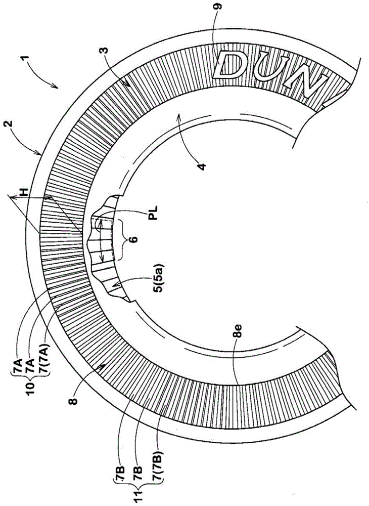
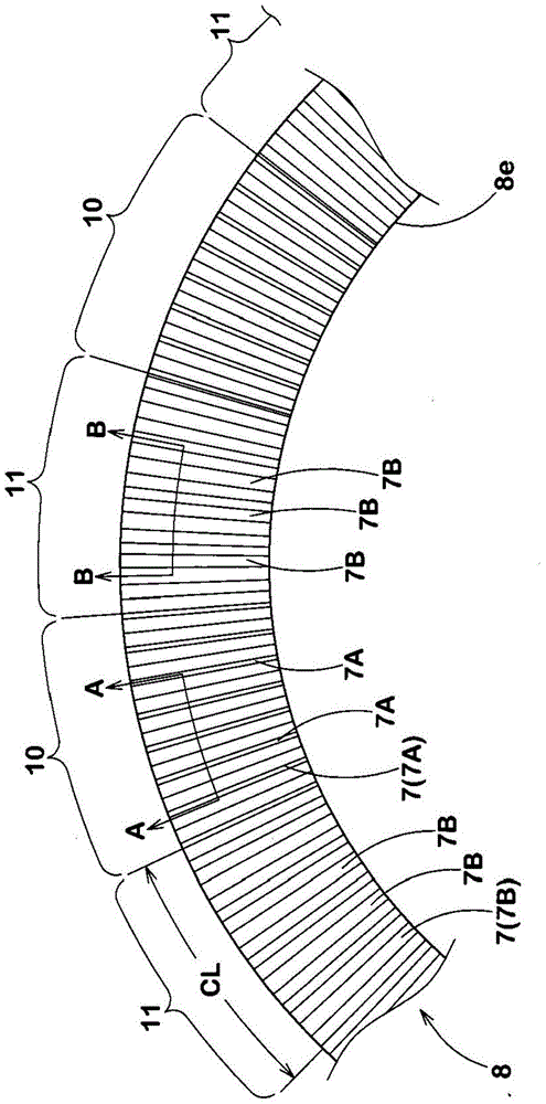
[0044] In order to confirm the effects of the present invention, various pneumatic tires with a size of 175 / 60R14 were trial-produced based on the specifications in Table 1, and an appearance evaluation test of the sidewall portion was performed. The number of carcass plies in this pneumatic tire is one, and the length PL of the joint portion of the carcass plies at the inner edge of the decorative pattern is 12 mm. The decorative pattern is formed by arranging the first ridge group and the second ridge group alternately. Accordingly, a region where a decorative pattern is formed and a region where a decorative pattern is not formed are intentionally provided on the sidewall portion. In addition, see Image 6 As shown, three types of ridges are used in the present embodiment as ridges of the ridge group.

[0045] In addition, in the appearance evaluation test, 5 testers visually compared the area where the decorative pattern is formed and the area where the decorative patter...


PUM


Abstract

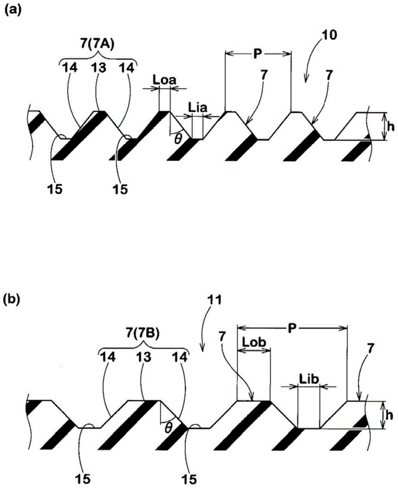
The invention provides a pneumatic tire improving a visual hiding effect of a concave part caused by a joint part of a tire body cord fabric on a tire side part, so that appearance deviation is prevented. The pneumatic tire is provided with a plurality of ridges in the periphery of the tire at intervals of 0.5 to 5.0 mm, so that an annular decorative pattern is formed. The decorative pattern includes more than two kinds of ridges having different section shapes and more than two and less than 17 ridges with the identical section arranged continuously form a pattern unit and the ridge groups of different kinds are arranged in the peripheral direction. Therefore, the above decorative pattern is formed. Cross sections of the ridges are generally trapezoid in shape. Namely, the cross section is provided with an outer surface part disposed outside the tire and a pair of inclined side face parts extending from two ends of the outer surface part to the inner side of the tire. The lengths of the outer surfaces of the two kinds of ridges with different section shapes and lengths of bottom parts disposed on the inner side of the tire connecting the adjacent ridges together are different.

Description

technical field [0001] The present invention relates to a pneumatic tire capable of improving the effect of visually hiding a recessed portion caused by a joint portion of carcass ply appearing in a sidewall portion, thereby preventing deterioration of the appearance. Background technique [0002] A pneumatic tire is reinforced by a carcass ply made up of layers of carcass cords. The carcass ply is formed into a ring shape by winding a sheet-shaped ply in the tire circumferential direction and joining (lapping) both ends of the ply with a small width. However, since the carcass ply is partially overlapped in two layers due to the joint portion, the rigidity of the joint portion is improved compared with other portions. Therefore, after the pneumatic tire is filled with air, it is difficult to extend the joint portion of the carcass ply, and in particular, a concave portion appears in the sidewall portion where the covering rubber is thin. Due to such recesses, there is a p...

Claims


Application Information

Patent Timeline
Patent Type & Authority Patents(China)
IPC IPC(8): B60C13/00
CPCB60C13/001B60C13/02
Inventor 池林宏之
Owner SUMITOMO RUBBER IND LTD
Learn More