Cab structure of urban rail

A driver's cab and urban rail technology, which is applied in the field of urban rail driver's cab structure, can solve the problems that affect the arrangement of the equipment in the driver's cab, the headlights can only be arranged horizontally, and cannot meet the requirements, etc. The effect of design difficulty

Active Publication Date: 2014-03-26
ZHUZHOU ELECTRIC LOCOMOTIVE CO
View PDF5 Cites 12 Cited by
  • Summary
  • Abstract
  • Description
  • Claims
  • Application Information

AI Technical Summary

Problems solved by technology

At present, there are few studies on the cab structure in the industry. The existing B-type urban rail vehicle cab structure can only bear 800kN compressive load and 640kN tensile load; for the 300kN compressive load requirement under the front window, it basically cannot meet the requirements
And to ensure safety, if figure 1 As shown, the driver's cab generally adopts a mesh structure, and the front beam 10 is set to strengthen anti-collision. The complex structure occupies a lot of space and affects the layout of the equipment in the driver's cab.
Due to the existence of the front beam 10, it is troublesome to install the hood outside the driver's room, and the headlights can only be arranged horizontally instead of vertically.

Method used


Image

  • Cab structure of urban rail
  • Cab structure of urban rail
  • Cab structure of urban rail

Examples


Embodiment Construction

[0028] It should be noted that, in the case of no conflict, the embodiments of the present invention and the features in the embodiments can be combined with each other. The present invention will be described in detail below with reference to the accompanying drawings and examples.

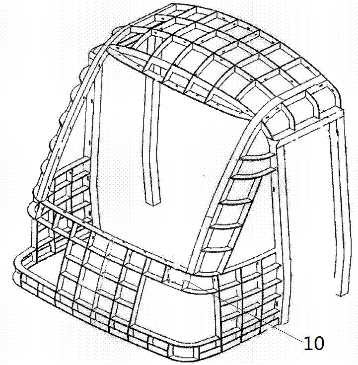
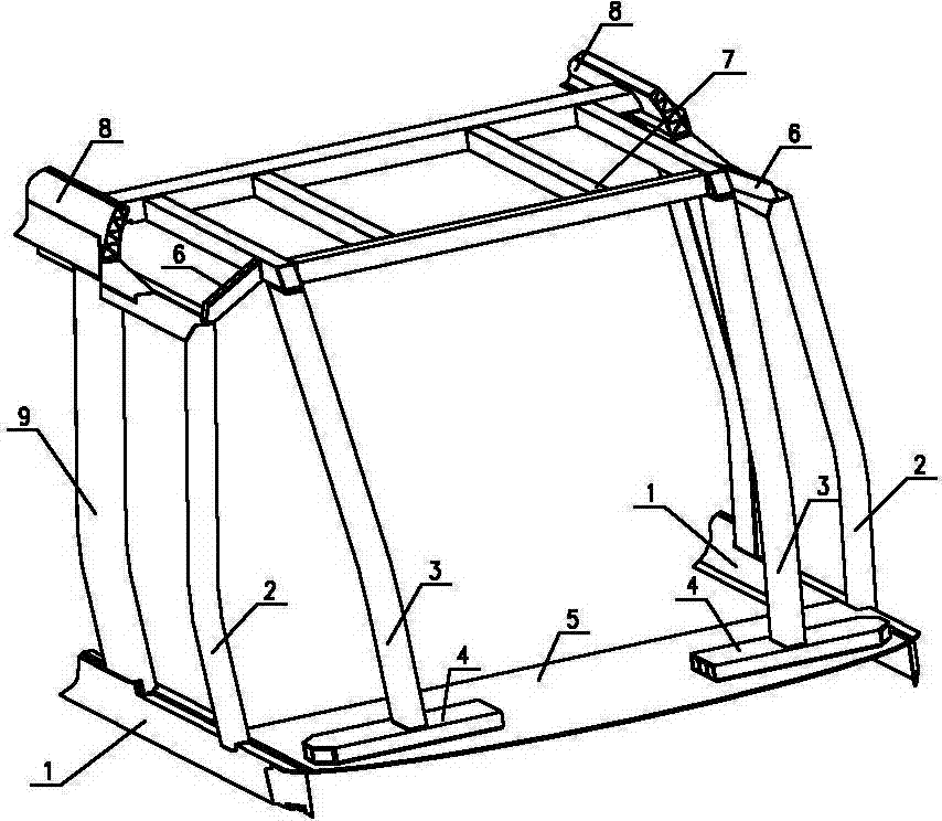
[0029] like image 3 Shown, a kind of urban rail driver's cab structure, it comprises underframe side beam 1, inverted L-shaped driver's cab door column 2, front end floor 5, roof side beam 8 and side wall door column 9; Front end floor 5 two ends and The bottom frame side beam 1 is connected; the side wall door column 9 is connected with the top cover side beam 8 and the bottom frame side beam 1; There is a floor beam 4 on the top; the lower end of the inverted L-shaped driver's cab door column 2 is connected to the underframe side beam 1, and the upper end is connected to the end surface of the roof side beam 8; the front column 3 is connected to the floor beam 4 and the front beam of the mesh...


PUM


Abstract

The invention provides a cab structure of an urban rail. The cab structure comprises the side beams of a bottom frame, the vertical column of a reverse L-shaped cab door, floor on a front end, the side beam of a top cover and the vertical columns of a side wall door; both ends of the floor on the front end are connected with the side beams of the bottom frame; the vertical columns of the side wall door are connected with the side beam of the top cover and the side beams of the bottom frame; a vertical column on the front end, the cross beam of the floor, a support side beam and an assembly structure in the shape of Chinese character Mu are also arranged; the cross beam of the floor is arranged on the floor on the front end; the lower end of the vertical column of the reverse L-shaped cab door is connected with the side beams of the bottom frame, and the upper end of the vertical column is connected with the end surface of the side beam of the top cover; the vertical column on the front end is connected with the cross beam of the floor and the front cross beam of the assembly structure in the shape of Chinese character Mu; the rear cross beam of the assembly structure in the shape of Chinese character Mu extends towards both ends and is connected with the side beam of the top cover; one end of the support side beam is connected with the vertical column of the reverse L-shaped cab door, and the other end of the support side beam is connected with the assembly structure in the shape of Chinese character Mu. According to the cab structure of the urban rail, the structural shape is simple, and the strength and rigidity are high; interfaces among all structures of the cab and between the structures and the bottom frame, a side wall and the top cover are simple, the process technique is good, and the manufacturing cost is reduced.

Description

technical field [0001] The invention relates to the field of locomotive structures, in particular to an urban rail cab structure. Background technique [0002] For urban rail trains, the driver's cab is located at the forefront and is the first "window" facing the outside world. Its design must consider safety, aesthetics, practicality and other factors. At present, there are few studies on the cab structure in the industry. The existing B-type urban rail vehicle cab structure can only bear 800kN compressive load and 640kN tensile load; the 300kN compressive load requirement under the front window basically cannot meet the requirements. And to ensure safety, if figure 1 As shown, the driver's cab generally adopts a mesh structure, and the front beam 10 is set to reinforce the anti-collision. The complex structure occupies more space, which affects the layout of the equipment in the driver's cab. Due to the existence of the head beam 10, the driver's outdoor hood is trouble...

Claims


Application Information

Patent Timeline
Patent Type & Authority Applications(China)
IPC IPC(8): B61C17/04
Inventor 岳译新苏柯刘永强刘亚妮银应时
Owner ZHUZHOU ELECTRIC LOCOMOTIVE CO
Why Eureka
Try Eureka