Air-conditioner unit air duct system for vehicle

A vehicle-used air conditioner and air-conditioning unit technology, applied in the field of transportation, can solve the problems of increasing energy consumption of air-conditioning units, large return air resistance, and large fan pressure head, so as to reduce pressure head, reduce return air resistance, and reduce energy waste Effect

Active Publication Date: 2014-03-26
CRRC QINGDAO SIFANG CO LTD
View PDF9 Cites 7 Cited by
  • Summary
  • Abstract
  • Description
  • Claims
  • Application Information

AI Technical Summary

Problems solved by technology

[0003] The intercity vehicles in the prior art adopt the main air supply channel in the middle of the roof, the main air return channel on both sides of the main air supply channel, and the return air outlet at the end of the vehicle, and the return air outlet communicates with the main return air channel

Method used


Image

  • Air-conditioner unit air duct system for vehicle
  • Air-conditioner unit air duct system for vehicle
  • Air-conditioner unit air duct system for vehicle

Examples


Example Embodiment

[0024] The invention discloses an air duct system for a vehicle air conditioning unit to reduce the return air resistance of the main air return duct.

[0025] The technical solutions in the embodiments of the present invention will be clearly and completely described below in conjunction with the accompanying drawings in the embodiments of the present invention. Obviously, the described embodiments are only a part of the embodiments of the present invention, rather than all the embodiments. Based on the embodiments of the present invention, all other embodiments obtained by those of ordinary skill in the art without creative work shall fall within the protection scope of the present invention.
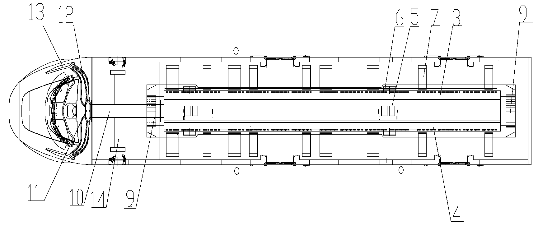
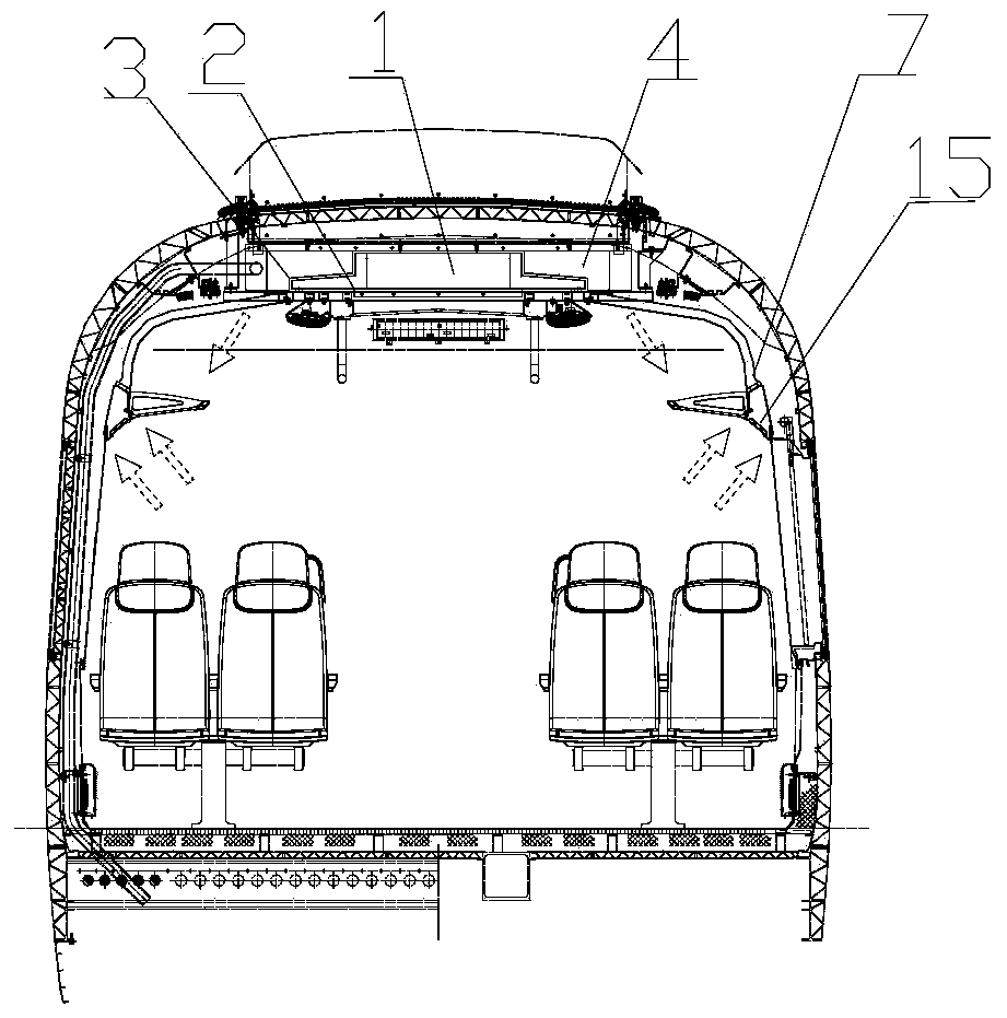
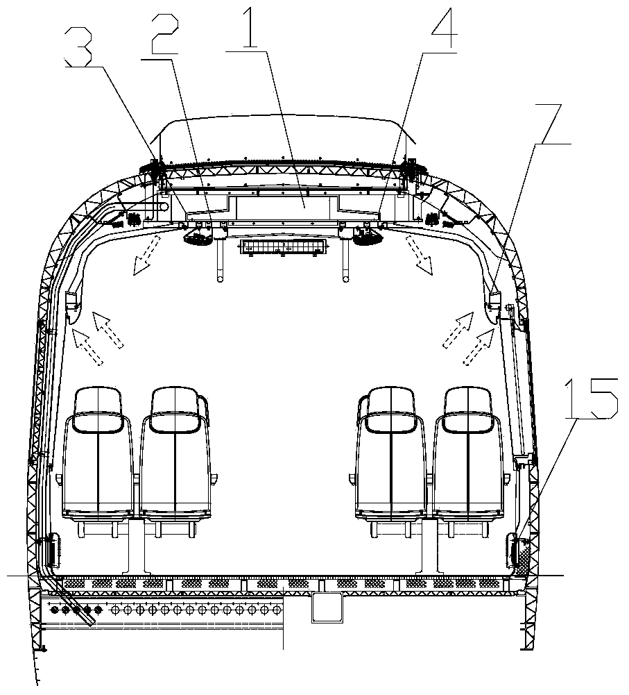
[0026] See Figure 1-Figure 5 , figure 1 Is a schematic structural diagram of an air duct system for a vehicle air conditioning unit provided by an embodiment of the present invention; figure 2 It is the first arrangement form of the return air cavity of the air duct system of the vehicle...


PUM


Abstract

The invention discloses an air-conditioner unit air duct system for a vehicle. The air-conditioner unit air duct system comprises a main air supply duct, a first air return duct and a second air return duct. The first air return duct and the second air return duct are arranged on the two sides of the main air supply duct. The main air supply duct is communicated with a compartment. Air-conditioner unit air return inlets communicated with an air-conditioner unit are formed in the first air return duct and the second air return duct. An air-conditioner unit air supply inlet communicated with the air-conditioner unit is formed in the main air supply duct. The air-conditioner unit air duct system further comprises a plurality of air return branch pipes communicated with the first air return duct and the second air return duct. One end of each air return branch pipe is communicated with the first air return duct or the second air return duct, and the other end of each air return branch pipe is communicated with the compartment. It can be seen from the technical scheme that the air return branch pipes are arranged on the first air return duct and the second air return duct and used for dispersing air entering the first air return duct and the second air return duct, return air dispersion is achieved, the resistance of return air inside the first air return duct and the second air return duct is reduced, a pressure head is reduced, the energy consumption of the air-conditioner unit is reduced, and the aim of reducing energy waste is achieved.

Description

technical field [0001] The invention relates to the technical field of transportation, in particular to an air duct system of a vehicle air-conditioning unit. Background technique [0002] Intercity trains generally refer to small and medium group short-distance passenger trains that run between two important cities that are not far apart, with multiple shifts and tend to be public transportation. Sleeper carriages can meet the traffic requirements of the rapid development of my country's regional economy and the rise of urban agglomerations, and have the characteristics of large passenger capacity and fast start and stop. [0003] The intercity vehicles in the prior art adopt the main air supply channel in the middle of the roof, the main air return channel on both sides of the main air supply channel, and the return air outlet at the end of the vehicle, and the return air outlet communicates with the main return air channel , All the air in the car enters the main air retu...

Claims


Application Information

Patent Timeline
IPC IPC(8): B61D27/00
Inventor 郭海霞于晓良王胜光袁博丁叁叁王军
Owner CRRC QINGDAO SIFANG CO LTD
Why Eureka
Try Eureka